PSSC complex girder
a girder and complex technology, applied in the direction of girders, bridges, joists, etc., can solve the problems of shortening the span length, reducing the durability of the girder, and limiting the long span and durability. , to achieve the effect of improving durability and prolonging the span
- Summary
- Abstract
- Description
- Claims
- Application Information
AI Technical Summary
Benefits of technology
Problems solved by technology
Method used
Image
Examples
first embodiment
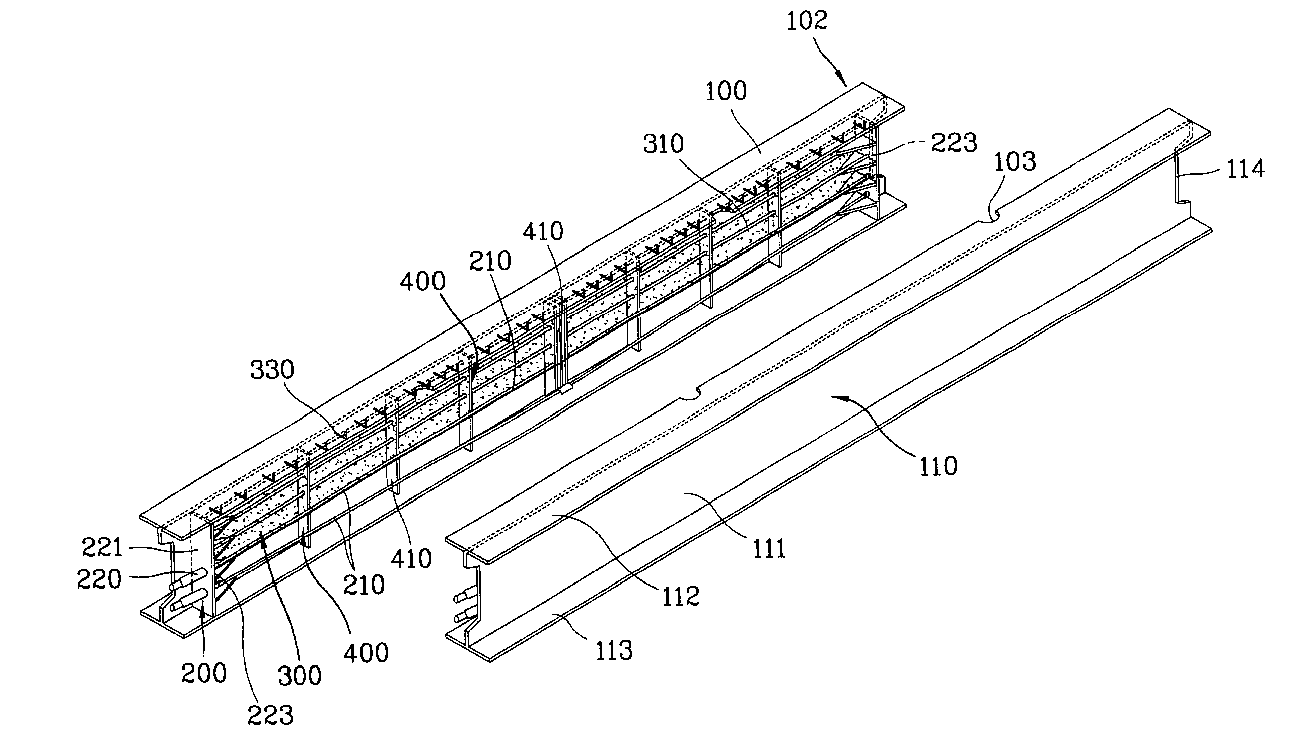
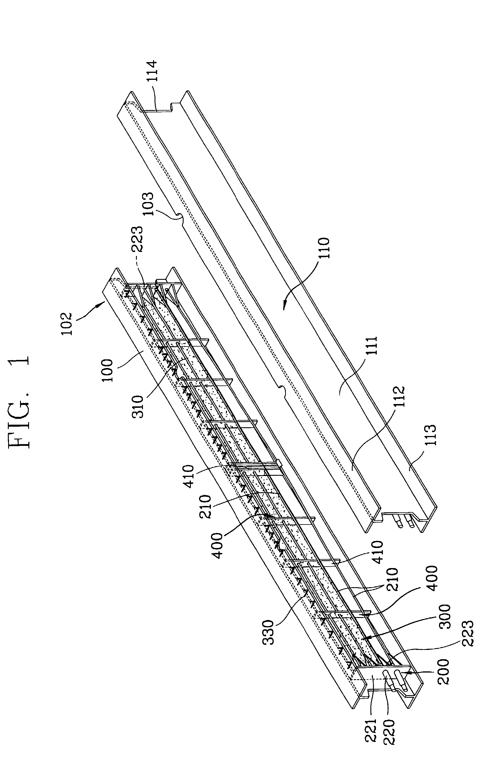
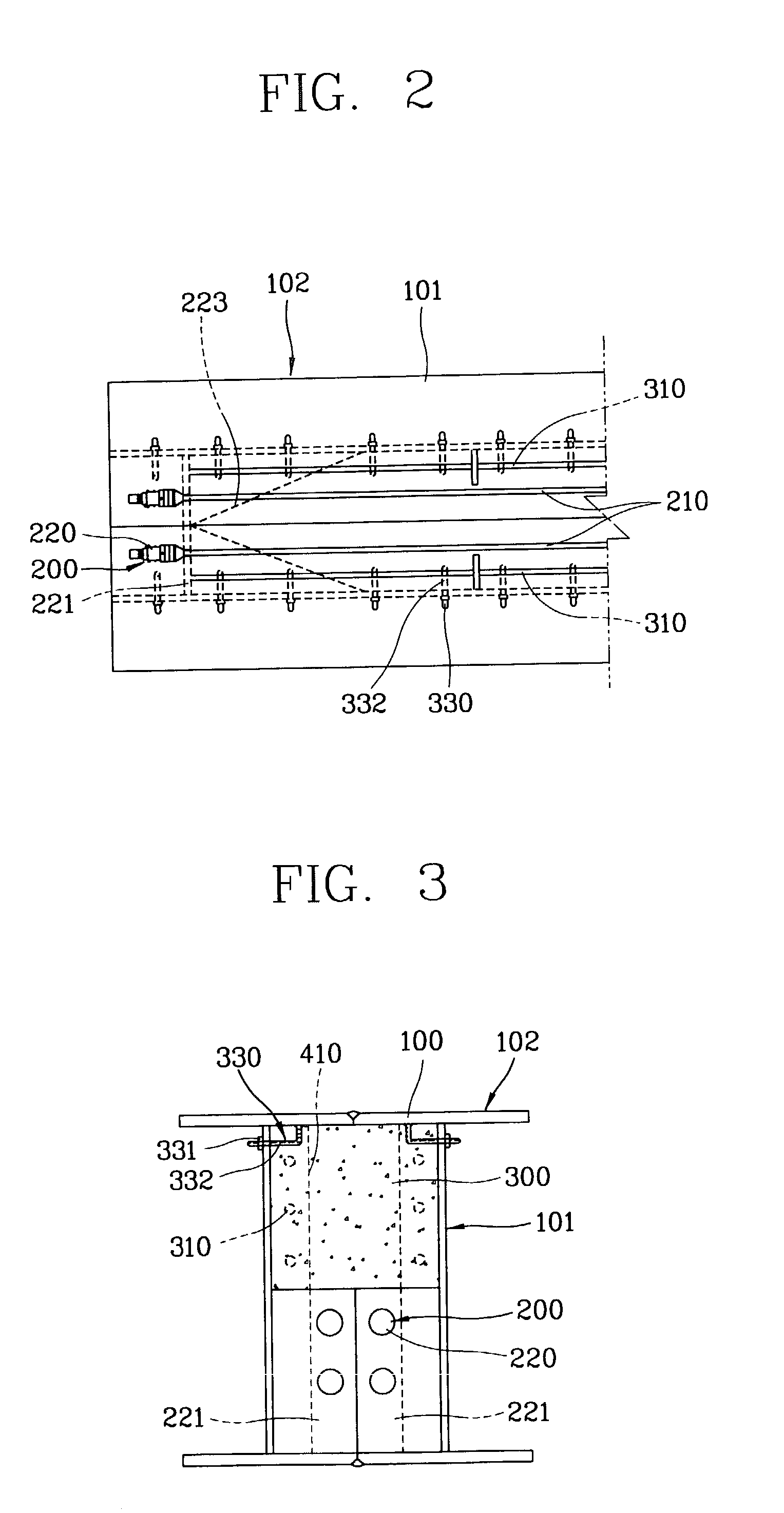
[0034]FIGS. 1 to 5B show a complex girder in accordance with the present invention. FIG. 1 is an unfolded perspective view showing a complex girder. FIG. 2 is a partial plan view showing the complex girder. FIG. 3 is a partially-sectional side view showing the complex girder. FIG. 4 is a partial front view showing the complex girder. FIGS. 5A and 5B are partially-sectional perspective views showing a changed shape of the complex girder by applying pre-stress to the complex girder to have camber.
[0035]As shown in the drawings, tension means 200 mounts both end portions of a tensional member 210 in the section shape steel structure 102. The section shape steel structure 102 is made of section shape steel 100, such as an I-section shape steel or an H-section shape steel. Tensioned end portions of the tensional members 210, are joined to the section shapes steel to form the PSSC complex girder in accordance with the present invention. Concrete 300 is poured into the inner space of the s...
second embodiment
[0052]In the PSSC complex girder of the present invention, each settlement fixing plate 222 is fixed to both end portions of the section shape steel assembly 101, and both end portions of the tensional member 210 are inserted through holes formed in a row in the middle of the settlement fixing plates 222 to extend outside of the section shape steel structure 102. The tensional member is fixed in the holes by the settlement member 220.
[0053]Accordingly, the tensional members 210 are fixed in two rows at both end portions of the section shape steel assembly 101. Inside both section shape steel 100, strengthening means 400 for preventing buckling are respectively disposed between the web portion 111 of the side member 110 and the upper and lower flanges 112 and 113. A plurality of sheer prevention members 330 is also disposed inside of respective webs 111. Steel reinforcements 310 are arranged in the inner space portion of both the section shape steel 100 and the concrete 300 is poured...
third embodiment
[0054]FIGS. 10 to 12 illustrate an exploded unfolded perspective view, partially-sectional side view showing a complex girder in accordance with the present invention and a partially-sectional perspective view showing cambered shape, respectively.
[0055]As shown in the drawings, in the PSSC complex girder in accordance with the third embodiment of the present invention, the section shape steel 100 are vertically mounted and joined by a plurality of high-tensile bolt 120 fixed by nuts. As in the first embodiment of FIGS. 1 to 5, in the side members 110, the tension means 200 includes a tensional member 210 and settlement member 220 that are fixed in two rows to both end portions of the section shape steel assembly 101. In addition, the strengthening means 400 and concrete 300 are connected to both end portions of the section shape steel assembly 101.
PUM
 Abstract
Description
Claims
Application Information
 - R&D
- Intellectual Property
- Life Sciences
- Materials
- Tech Scout
- Unparalleled Data Quality
- Higher Quality Content
- 60% Fewer Hallucinations
Browse by: Latest US Patents, China's latest patents, Technical Efficacy Thesaurus, Application Domain, Technology Topic, Popular Technical Reports.
© 2025 PatSnap. All rights reserved.Legal|Privacy policy|Modern Slavery Act Transparency Statement|Sitemap|About US| Contact US: help@patsnap.com


