Single clutch layshaft transmission

a transmission and single clutch technology, applied in mechanical equipment, transportation and packaging, gear shifting, etc., can solve the problems of low quality gear ratio change, adversely affecting fuel economy, etc., and achieve the effect of reducing drag loss

Inactive Publication Date: 2006-09-19
FORD GLOBAL TECH LLC
View PDF7 Cites 21 Cited by
  • Summary
  • Abstract
  • Description
  • Claims
  • Application Information

AI Technical Summary

Benefits of technology

[0005]A transmission according to the present invention includes only one friction clutch for releasably connecting a source of power, such as an engine or motor, and a transmission input. Gear ratio changes are accomplished through the use of couplers, such as synchronizers or dog clutches, which mutually driveably connect components operative in each speed ratio. The couplers produce very little drag loss when engaged, and do not require a continuous supply of power to stay engaged.
[0006]Power interruption during shifting is avoided by providing alternate power paths, which transmit power between a transmission input and the output during a gear ratio change. A secondary power path bypasses the friction clutch, but contains a one-way clutch. Before starting an upshift from an initial gear to a higher gear, one power path is set for a slightly lower speed ratio than the initial gear by engaging synchronizers or dog clutches, thereby causing the one-way clutch to overrun. In order to transfer power to the second torque path, the friction clutch is released and the secondary power path carries torque through the one-way clutch. Transfer of torque to the secondary power path is essentially a downshift to a speed ratio that is slightly lower than the current or off-going gear ratio.

Problems solved by technology

Automatic transmissions for transmitting power between an input and an output, either over a continuously variable range of speed ratios or in discrete step changes among speed ratios, have associated with them several sources of parasitic losses, which adversely affect fuel economy.
These losses are associated with a torque converter, open friction clutches and brakes, hydraulic pump, and gear meshes.
This requirement can result in low quality gear ratio changes, which a vehicle operator or passenger may sense as noise, vibration and harshness.

Method used


Image

  • Single clutch layshaft transmission
  • Single clutch layshaft transmission
  • Single clutch layshaft transmission

Examples


Embodiment Construction

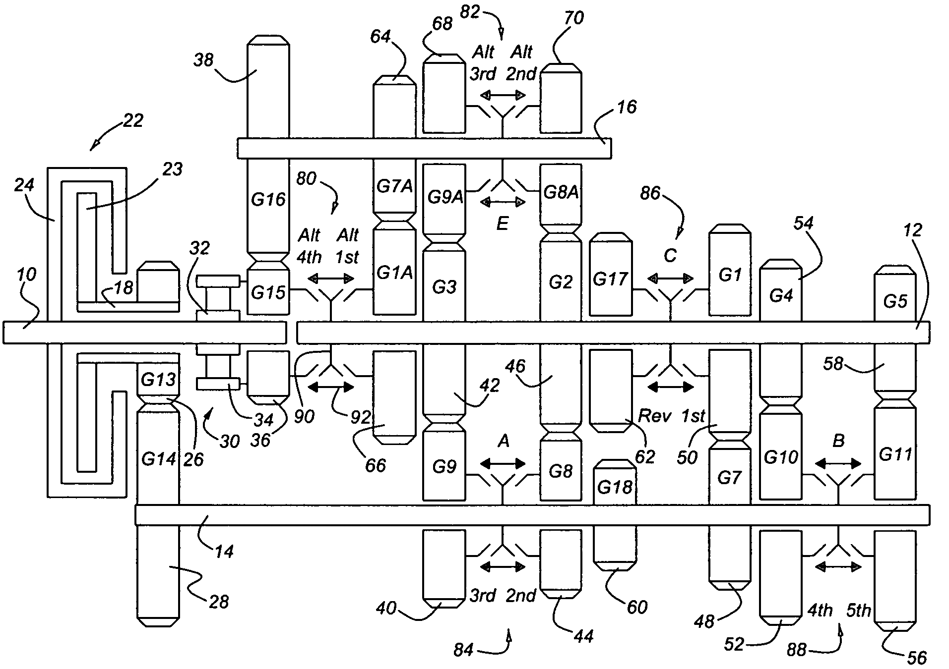
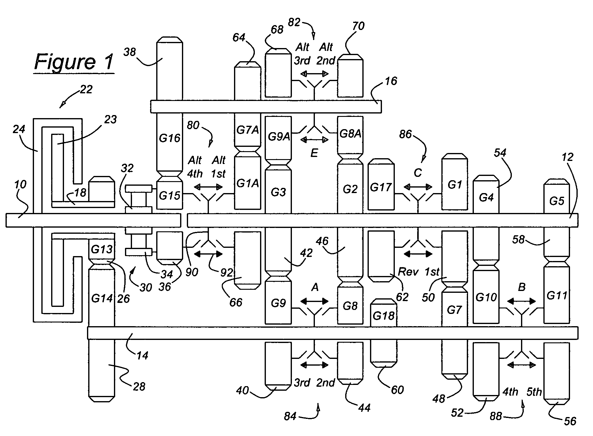
[0024]Referring now to the drawings, there is illustrated in FIG. 1 a transmission according to the present invention that includes an input 10 for driveably connecting a power source such as an internal combustion engine or electric motor to the transmission, and an output 12 for driving a load, such as the driven wheels of a motor vehicle, through a powertrain that may include a drive shaft, differential mechanism and axle shafts.

[0025]A primary layshaft 14 and secondary layshaft 16 are arranged substantially parallel to the output 12. A clutched input shaft 18, preferably substantially aligned with input 10, is releasably connected to the input through a friction clutch 22, whose output element 23 frictionally engages the clutch's input element 24 when the clutch is engaged. The input element 24 is secured to input 10. Layshaft 14 carries pinions and gears that are in continually meshing engagement with gears and pinions, respectively, on the clutched input shaft 18 and output 12...


PUM


Abstract

A transmission includes an input, a first layshaft, a second layshaft, a first power path for transmitting power between the input and first layshaft and producing a first ratio of a speed of the first layshaft and a corresponding speed of the input, a second power path for transmitting power between the input and second layshaft and producing a second ratio of the speed of the second layshaft and corresponding speed of the input; and a clutch for releasably connecting the input and the output.

Description

BACKGROUND OF THE INVENTION[0001]This invention pertains to the field of automatic shift manual transmissions and select shift manual transmissions, particularly to the types of these transmissions applicable to motor vehicles.[0002]Automatic transmissions for transmitting power between an input and an output, either over a continuously variable range of speed ratios or in discrete step changes among speed ratios, have associated with them several sources of parasitic losses, which adversely affect fuel economy. These losses are associated with a torque converter, open friction clutches and brakes, hydraulic pump, and gear meshes.[0003]To improve fuel economy in a motor vehicle having an automatic transmission, an automated shift manual (ASM) transmission can be used to eliminate or substantially reduce all of these parasitic losses except gear mesh losses. Such transmissions generally produce gear ratio changes by first interrupting torque transmitted from the engine to the transmi...

Claims


Application Information

Patent Timeline
Patent Type & Authority Patents(United States)
IPC IPC(8): F16H3/08F16H3/00F16H3/097
CPCF16H3/006F16H3/097F16H2003/0811Y10T74/19233F16H2200/0047F16H2200/0052Y10T74/19242F16H2003/0818
Inventor BALDWIN, REIDJANSON, DAVID
Owner FORD GLOBAL TECH LLC
Why Eureka
Try Eureka