Method for multiple lift stacking using mobile conveyor system

a conveyor system and mobile technology, applied in the direction of earthwork drilling, loading/unloading, surface mining, etc., can solve the problems of requiring a great deal of additional earthwork effort, a large amount of labor to extend and retract the overland conveyor, and the system takes a long time to move any appreciable distance, etc., to achieve the effect of reducing down time and improving flexibility and speed

Inactive Publication Date: 2006-09-19
TERRANOVA TECH
View PDF13 Cites 16 Cited by
  • Summary
  • Abstract
  • Description
  • Claims
  • Application Information

AI Technical Summary

Benefits of technology

[0011]Multiple lift pad and dump site stacking is enhanced in flexibility and speed by the use of mobile stackers, mobile trippers, and mobile conveyor modules, which are carried by rolling stock, such as wheels or crawler tracks which are steerable. Some of these modules are also self-powered so they are driveable to the required locations. The combination of mobile conveyor modules bringing aggregate to a tripper for distribution to a bridge stacker and a radial stacker provides efficient multiple lift stacking of a leach pad or a general dump site. Berm building and corridor filling occur at about the same time as the lift stacking. Moreover, the self-powered mobility of the mobile conveyor modules and tripper modules considerably reduces down time when the modules must be relocated.

Problems solved by technology

One of the problems with the conveyor systems of the prior art is that such systems take time to move any appreciable distance when a new stack is to be started.
Prior art multiple lift stacking systems using bridges, with either advance or retreat stacking, require considerable down time, a great deal of additional earth work effort, and a considerable amount of labor to extend and retract the overland conveyor used in the process.
The prior art stacking processes delay recovery of the metals or minerals of interest from the aggregate.
These concerns, in general, require movement of the prior art systems that could be both wasteful and unnecessary.

Method used


Image

  • Method for multiple lift stacking using mobile conveyor system
  • Method for multiple lift stacking using mobile conveyor system
  • Method for multiple lift stacking using mobile conveyor system

Examples


Embodiment Construction

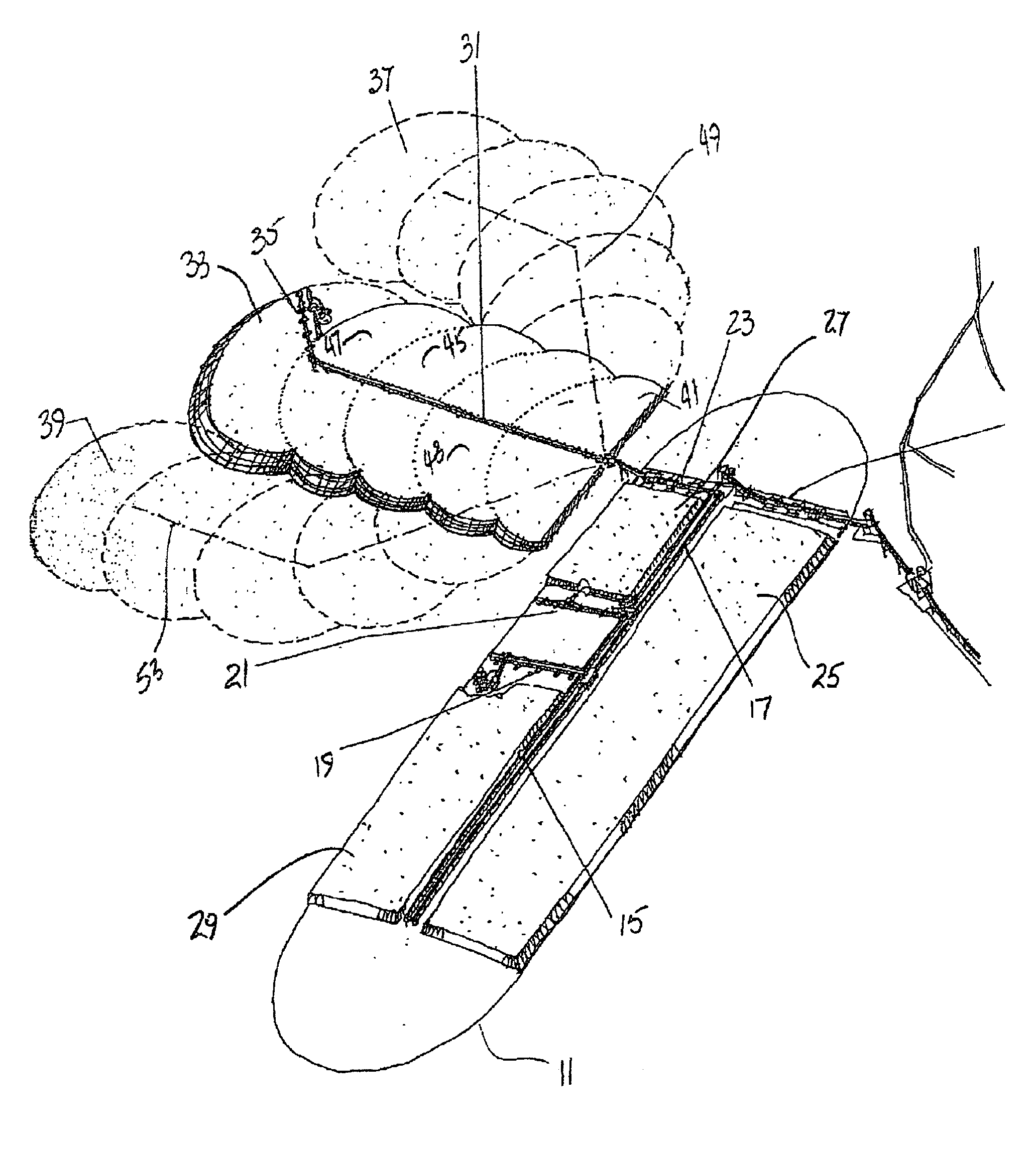
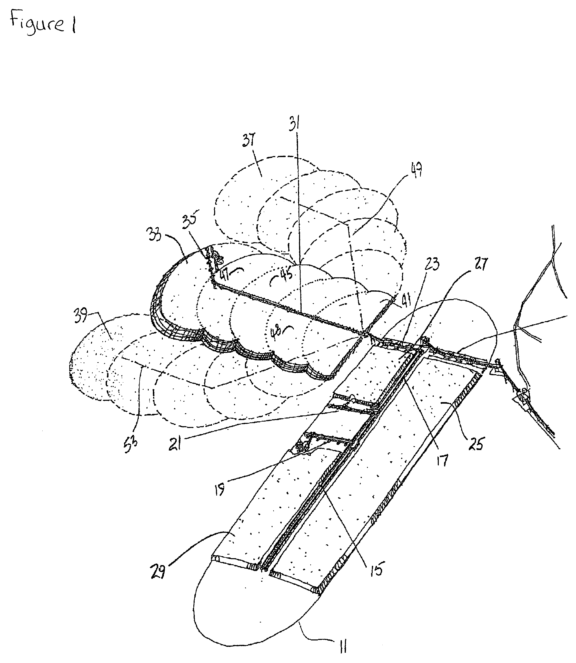
[0036]FIG. 1 illustrates in three dimensions and schematically one of many possible layouts for an on / off leach pad stacking scheme adjacent to a dump site. The stacking of the leach pad and dump site is being accomplished by prior art equipment. The conveyor modules of the present invention are not being used. Leach pad 11 is typically designed to capture the leach liquid and the contained dissolved recoverable minerals or metals. A discharge conveyor 13 delivers aggregate to a stacking overland conveyor 15, which is aligned parallel to the longer axis of the leach pad 11. Overland conveyor 15 supplies the aggregate to bridge stacker 21, which is shown retreat stacking a lift 27.

[0037]Ahead of bridge stacker 21, a reclaim bridge conveyor and associated equipment 19, removes the leached aggregate lift 29 from its path. This reclaimed aggregate is mostly unwanted residue. The removed aggregate is supplied to reclaim overland conveyor 17. Overland conveyor 17 transfers the aggregate t...


PUM


Abstract

Mobile conveyor modules are used for transporting aggregate over a long distance, or for transferring the aggregate to other modules, and for stacking the aggregate either linearly or radially. These modules may be used in various combinations by themselves or in combination with existing conveyor systems and bridge stackers to stack aggregate on and off multi-lift leach pads and on multi-lift dump sites. Multiple stacking methods may be used with mobile conveyor modules either separately, or at the same time, advance and retreat stacking, the stacking of a berm, or the filling in or a corridor, may be accomplished on a variety of terrain.

Description

CROSS REFERENCE TO RELATED APPLICATIONS[0001]This application is a divisional application of U.S. application Ser. No. 10 / 058,949 filed Jan. 28, 2002, now U.S. Pat. No. 6,782,993 entitled MOBILE CONVEYOR SYSTEM AND METHOD FOR MULTIPLE LIFT STACKING.STATEMENT REGARDING FEDERALLY SPONSORED RESEARCH OR DEVELOPMENT[0002]Not ApplicableREFERENCE TO SEQUENCE LISTING, A TABLE, OR A COMPUTER PROGRAM LISTING COMPACT DISK APPENDIX[0003]Not ApplicableBACKGROUND OF THE INVENTION[0004]The present invention relates to the movement of bulk materials, and more particularly, pertains to moving and stacking material, such as ore, coal, granite, clay, salt, and potash, generally referred to herein as “aggregate”, by mobile belt conveyor modules.[0005]The present invention is concerned with depositing aggregate into piles, and more particularly is an improved method for depositing aggregate into multi-lift dump sites, such as heap leach stacks, waste dump sites, or material dump sites, for example.[0006...

Claims


Application Information

Patent Timeline
Patent Type & Authority Patents(United States)
IPC IPC(8): B65G47/00E21C37/00B65G41/00B65G65/28
CPCB65G65/28B65G41/008
Inventor BERNARD, GEORGE MKELLY, RONALD R
Owner TERRANOVA TECH
Why Eureka
Try Eureka