Structure of stacked inkjet head

a technology of stacked inkjet head and connection structure, which is applied in printing and other directions, can solve the problems of unstable etching speed and people's complicated manufacturing processes, and achieve the effect of improving the situation of inhomogeneous etching and complicating manufacturing processes

Active Publication Date: 2006-09-19
TRANSPACIFIC IP LTD
View PDF8 Cites 7 Cited by
  • Summary
  • Abstract
  • Description
  • Claims
  • Application Information

AI Technical Summary

Benefits of technology

[0009]In order to solve the problems caused by alignment and clogging, people often complicate the manufacturing processes. The invention provides a stacked inkjet head structure. We use a special structure design to solve the problems of adhesive clogging, weak connection strengths, and cracks. At the same time, the invention can improve the situation of inhomogeneous etching for making nozzles or channels.
[0010]The disclosed structure of a stacked inkjet head is comprised of a stacked fluid structure and an actuator. The stacked fluid structure has more than one fluid channel, ink cavity, and nozzle. The fluid channels provide the passages for a fluid to enter the ink cavities. The ink cavities eject the fluid out of the nozzles when they are under pressure. The stacked fluid structure is formed with a plurality of plates. Each plate has several through holes that are connected with one another to form the fluid channels, ink cavities, and nozzles. In the plates, the junction surface of at least one plate has more than one adjusting hole. The actuator is connected to the stacked fluid structure to put a pressure on the ink cavities. The plate with the adjusting holes has a smaller contact area. Under the same pressure, the stress on a unit area can increase. The adjusting holes also results in a larger thermal expansion room for the whole stacked fluid structure, buffering the deformation caused by temperature or pressure. The stacked fluid structure further includes the adhesive coated on the junction surface of the plate to enhance the connection strength among the plates. The adjusting holes can accommodate the overflown adhesive to avoid the clogging of the channels or nozzles. The adjusting holes can also function as the controlling mechanism of the junction to increase the connection strength.
[0011]Moreover, the adjusting holes and through holes are formed on the plate with the adjusting holes by wet etching. Generally speaking, if the area or size of the through holes on the plate varies a lot, the etching speed may be unstable. However, etching the adjusting holes at the same time can balance the overall etching speed to reach the goal of accurately control the etching precision.

Problems solved by technology

In order to solve the problems caused by alignment and clogging, people often complicate the manufacturing processes.
Generally speaking, if the area or size of the through holes on the plate varies a lot, the etching speed may be unstable.

Method used


Image

  • Structure of stacked inkjet head
  • Structure of stacked inkjet head
  • Structure of stacked inkjet head

Examples


Embodiment Construction

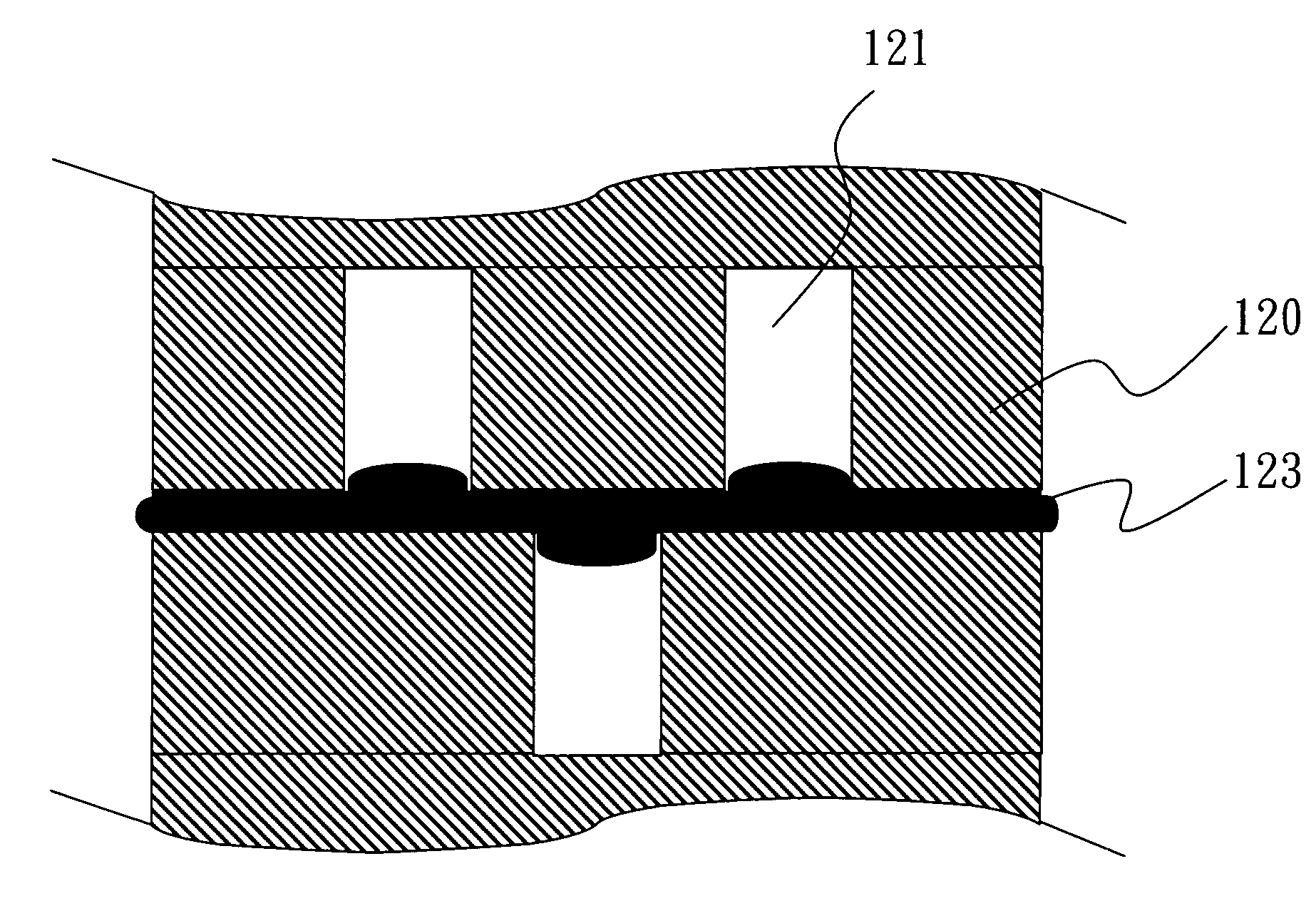
[0017]The stacked inkjet head structure of the invention makes use of a plate with adjusting holes. The adjusting hole design solves the problems of adhesive clogging, insufficient connection strength and cracks. Since the disclosed structure can be easily assembled, the manufacturing cost and difficulty are lowered.

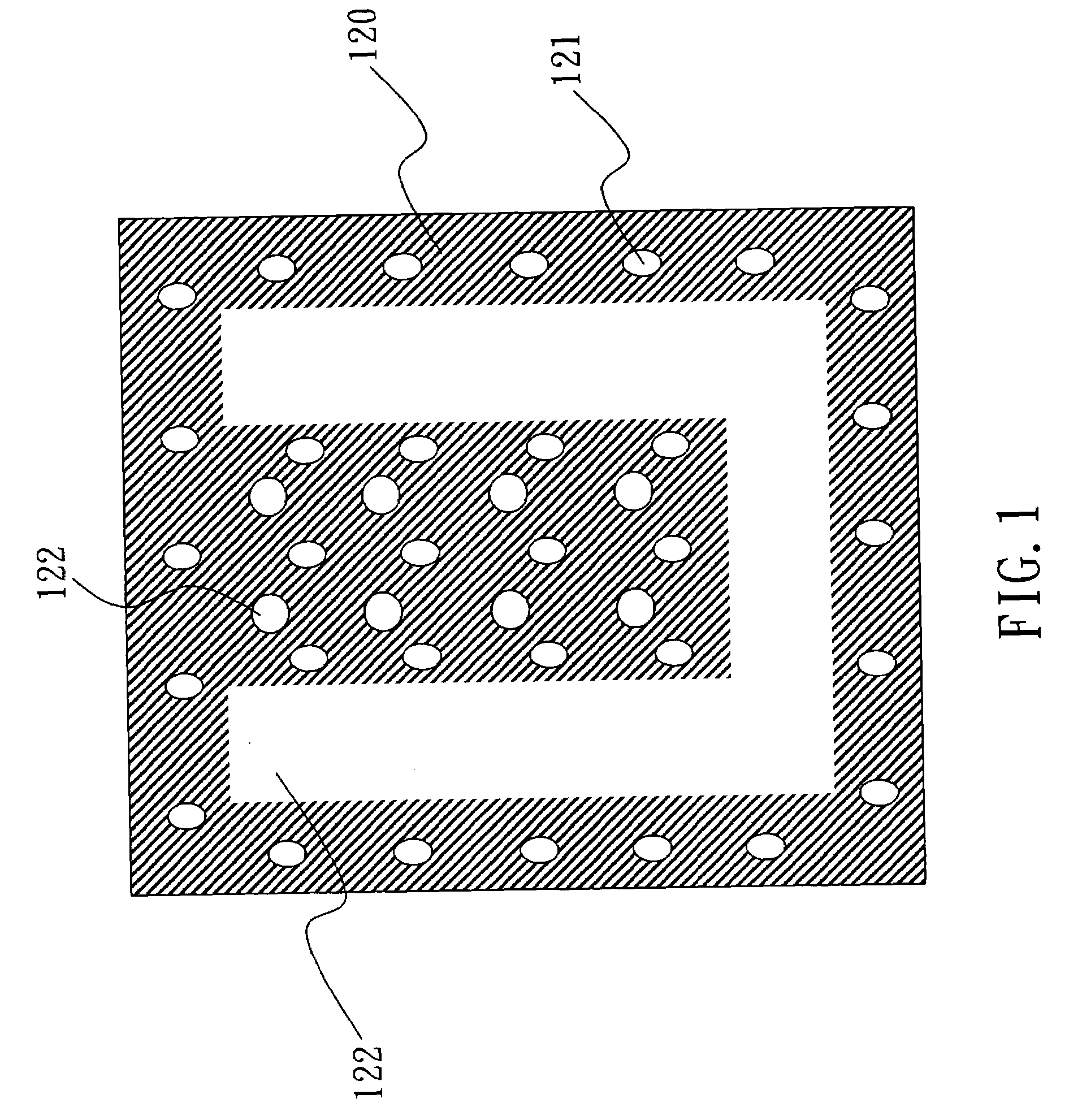
[0018]With reference to FIG. 1, the plate 120 has several through holes 122 and adjusting holes 121. The through holes 122 can be divided into the channel through holes with a larger size and the nozzles with a smaller size. The adjusting holes 121 are homogeneously distributed on the junction surface of the plate 120. The adjusting holes can be penetrating holes or blind holes of the plate. The adjusting hole design can avoid the concentration of reacting ions at the channel through holes with a larger size when forming the channel through holes, nozzles, and adjusting holes by wet etching. The overall etching speed and hole sizes are thus more precisely controlled.

[001...


PUM


Abstract

A structure of the stacked inkjet head is composed of a stacked fluid structure and an actuator. At least one of the several plates in the stacked fluid structure has a junction with a tuning hole for enhancing the connection strength of the junction, accommodating overflown adhesive, and reducing structural deformation resulted from the temperature. The invention also avoids the troubles of inhomogeneous etching speeds when making nozzles or channels.

Description

[0001]This Non-provisional application claims priority under 35 U.S.C. § 119(a) on Patent Application Ser. No(s). 092131313 filed in Taiwan on Nov. 7, 2003, the entire contents of which are hereby incorporated by reference.BACKGROUND OF THE INVENTION[0002]1. Field of Invention[0003]The invention relates to a structure of inkjet head and, in particular, to a connection structure of a stacked inkjet head.[0004]2. Related Art[0005]The main technologies involved in inkjet print heads are piezoelectric inkjet heads and thermal bubble inkjet heads. The difference between them is whether the actuator used for pushing ink is of the thermal bubble type of the piezoelectric type. The thermal bubble actuator uses a heater to instantaneously vaporize ink, producing high-pressure bubbles to push ink out of nozzles. The piezoelectric actuator uses deformation of piezoelectric ceramics under an external voltage to push liquid out of nozzles. Relative to the thermal bubble type, the piezoelectric i...

Claims


Application Information

Patent Timeline
Patent Type & Authority Patents(United States)
IPC IPC(8): B41J2/045B41J2/16
CPCB41J2/14233B41J2/161B41J2/1623B41J2/1629B41J2/162B41J2002/14362
Inventor LU, CHUN-FUHSU, FA-YUANLIU, HOWARDWANG, CHENG-YICHEN, HUEN-LINGLO, CHI-BIN
Owner TRANSPACIFIC IP LTD
Why Eureka
Try Eureka