Power assisted drill press

a drill press and power technology, applied in the field of drill press devices, can solve the problems of inability to drill holes onto the surface, undesirable features, and heavy weight of conventional drill presses, and achieve the effect of quick and easy securing

Inactive Publication Date: 2006-09-19
MUELLER THOMAS L MUELLER TOD BEVERLY H & MUELLER JOSEPH E
View PDF43 Cites 49 Cited by
  • Summary
  • Abstract
  • Description
  • Claims
  • Application Information

AI Technical Summary

Benefits of technology

[0011]To accomplish the foregoing and other objects of this invention there is provided an improved power assisted drill press apparatus for use in applications where a drill press is desired or required. In a preferred embodiment, the apparatus comprises a drill motor and chuck combination which is mounted with a motor frame and linearly actuated via the force of a feed cylinder. Altern

Problems solved by technology

Unfortunately, a conventional drill press is often heavy, not portable, and unable to drill a hole onto a surface unless the work material is between the drill and drill press table or base.
Even the commercially available drill press stands w

Method used


Image

  • Power assisted drill press
  • Power assisted drill press
  • Power assisted drill press

Examples


Embodiment Construction

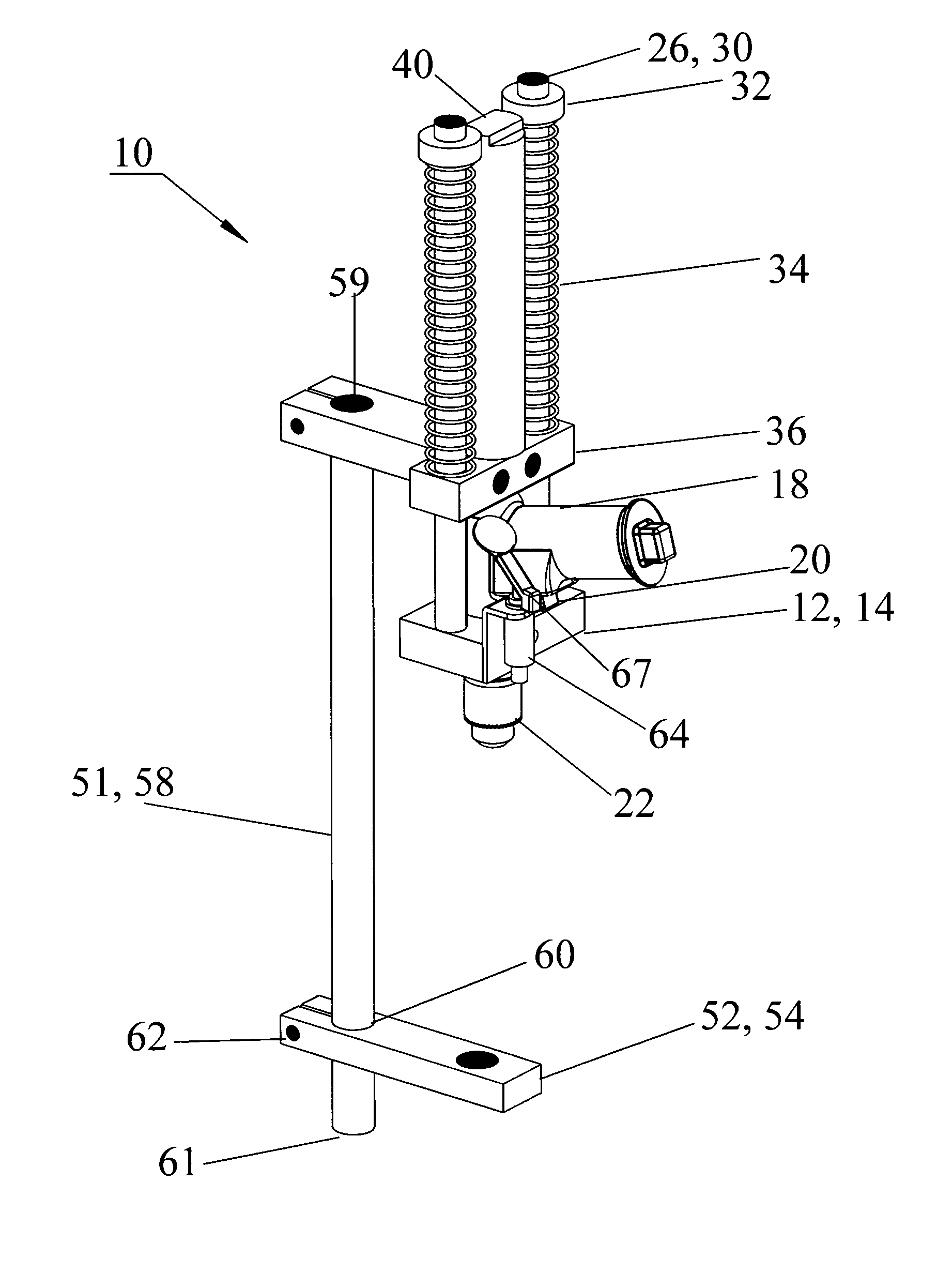
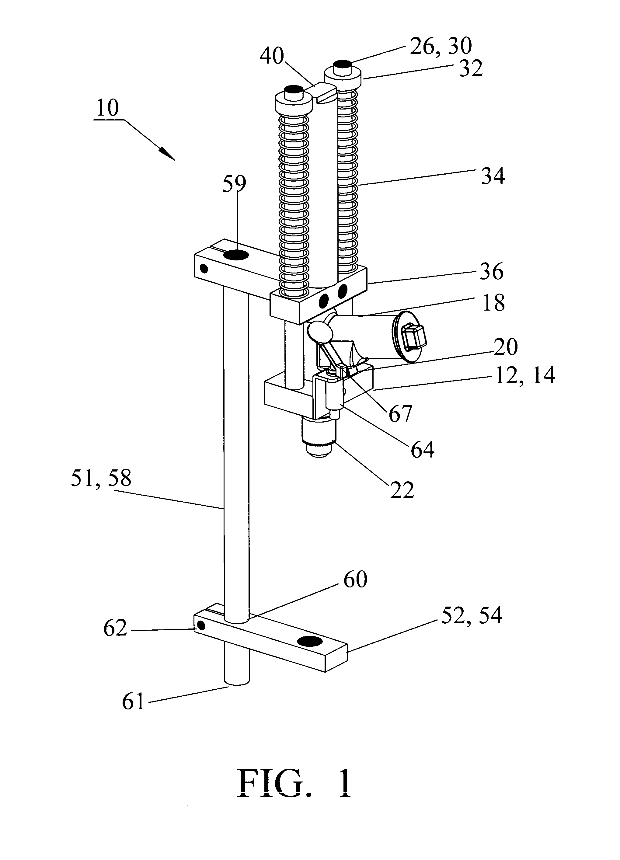
[0029]Referring now to the drawings, the improved power assisted drill press apparatus 10 is shown in its preferred and alternative embodiments. The apparatus 10 is especially useful in applications where a portable and self feeding drill press is desired or required and when said drill press requires non-destructive mounting on a non-magnetic surface.

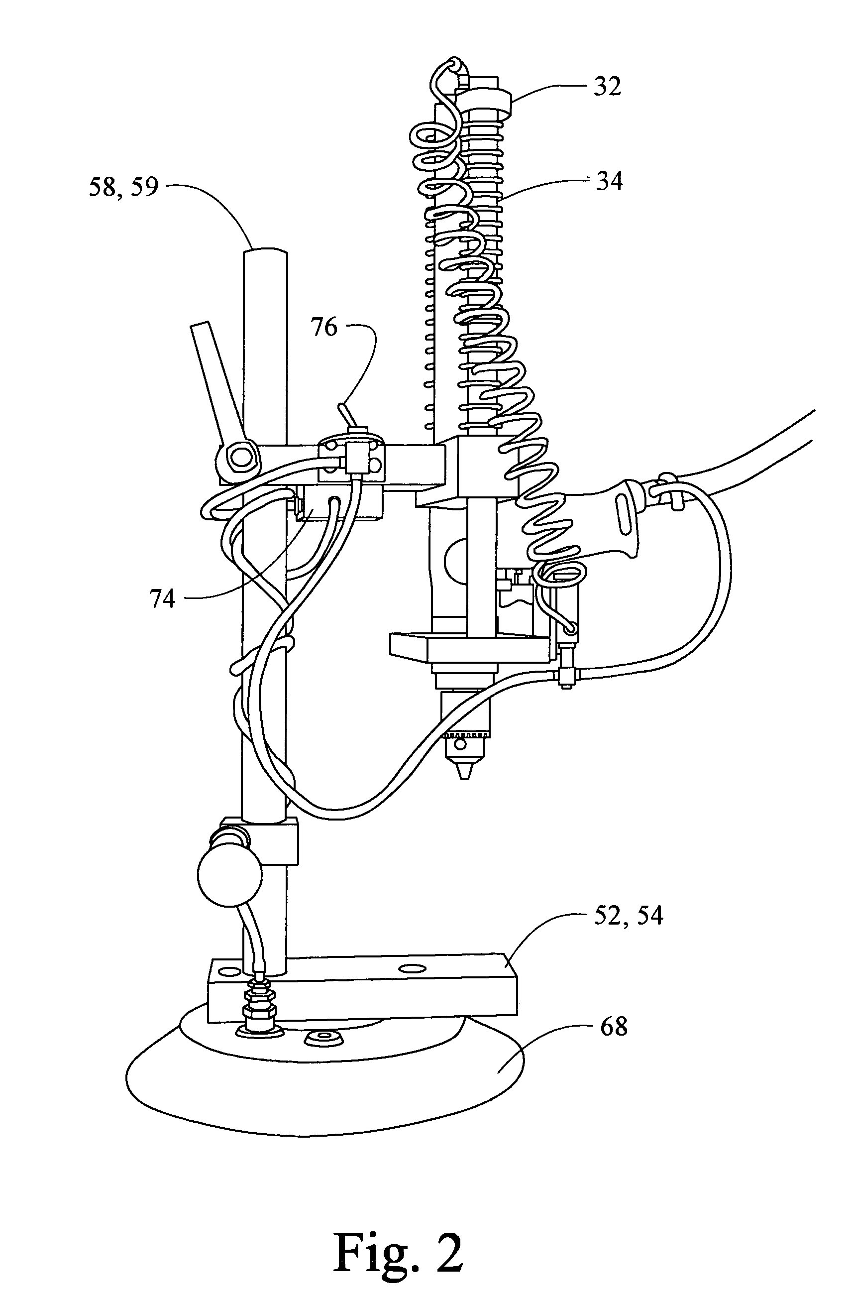
[0030]The present art overcomes the prior art limitations by providing a drill motor 18 and chuck 22 combination which is mounted with a motor frame 12 and linearly actuated via the force of a feed cylinder 40. Preferably, the feed cylinder 40 is a pneumatically actuated cylinder but may also be hydraulic, electromagnetic, or a mechanical force actuator. Also, the drill motor 18 is preferably a commercially available pneumatically operated hand held drill with attached chuck 22 but may also be electrically or hydraulically actuated, whether commercially available or custom built for the present art. The linearly moveable motor frame 12...


PUM

PropertyMeasurementUnit
Forceaaaaaaaaaa
Sizeaaaaaaaaaa
Circumferenceaaaaaaaaaa

Abstract

A power assisted drill press having a feed cylinder fed by a variable pressure regulator which allows a user to controllably feed a bit and work material together while activating a drill motor to rotate the bit. An embodiment of the power assisted drill press utilizes a suction cup and venturi system for attachment of the press to a surface work material. The drill press uniquely allows a person to variably activate the feed cylinder and also activate the drill motor with a single hand.

Description

[0001]This application claims priority of U.S. Provisional Patent Application No. 60 / 412,701, filed Sep. 23, 2002.BACKGROUND OF THE INVENTION[0002]The present invention relates in general to drill press devices, and more particularly, to a novel drill press apparatus having a controlled power assisting feed mechanism and a vacuum holding system.[0003]In a conventional drill press, a rack and pinion gear is typically used to linearly move the rotating drill chuck toward the work material. The rack and pinion system applies the force to the drill bit through said chuck. Said drill bit utilizes said force to bore through the work material. Unfortunately, a conventional drill press is often heavy, not portable, and unable to drill a hole onto a surface unless the work material is between the drill and drill press table or base. Even the commercially available drill press stands which utilize conventional hand held drill motors, exhibit the aforesaid undesirable features. Moreover, those...

Claims


Application Information

Patent Timeline
IPC IPC(8): B23B39/00B23G1/00B23B45/14B23B47/00B23B49/00
CPCB23B39/00B25H1/0057B25H1/0064B23C2270/025B23C2270/027Y10T408/6757Y10T408/554Y10T408/03Y10T408/5653
Inventor MUELLER, THOMAS L.
Owner MUELLER THOMAS L MUELLER TOD BEVERLY H & MUELLER JOSEPH E
Why Eureka
Try Eureka