Power supply apparatus for arc-utilizing apparatus

a technology of power supply apparatus and arc-utilizing apparatus, which is applied in the direction of electric variable regulation, instruments, manufacturing tools, etc., can solve the problems of preventing the reduction of size and weight of power supply apparatuses of this typ

Active Publication Date: 2006-09-19
SANSHA ELECTRIC MFG
View PDF7 Cites 11 Cited by
  • Summary
  • Abstract
  • Description
  • Claims
  • Application Information

AI Technical Summary

Benefits of technology

[0006]According to a first embodiment of the present invention, a power supply apparatus for an arc-utilizing apparatus includes an input rectifier for rectifying either one of two, higher and lower AC input voltages applied to its input. First and second inverters are connected in the output of the input rectifier. A high-frequency transformer is connected in the output of each of the first and second inverters. An output rectifier is connected in the output of each of the high-frequency transformers. A switching circuit operates to connect the first and second inverters in series with each other between output terminals of the input rectifier when the higher one of the two AC input voltages is applied to the input rectifier, and operates to connect the first and second inverters in parallel between the output terminals of the input rectifier when the lower one of the two AC input voltages is applied to the input rectifier. Voltage balancing control means operates to suppress imbalance between the input voltages as applied to the first and second inverters when the switching circuit is operating to connect the first and second inverters in series between the output terminals of the input rectifier.

Problems solved by technology

The power supply apparatus disclosed in this Japanese patent application publication requires tertiary windings in the high-frequency transformers, and diode bridges in association with the respective tertiary windings, which impedes reduction of size and weight of power supply apparatuses of this type.

Method used


Image

  • Power supply apparatus for arc-utilizing apparatus
  • Power supply apparatus for arc-utilizing apparatus
  • Power supply apparatus for arc-utilizing apparatus

Examples


Embodiment Construction

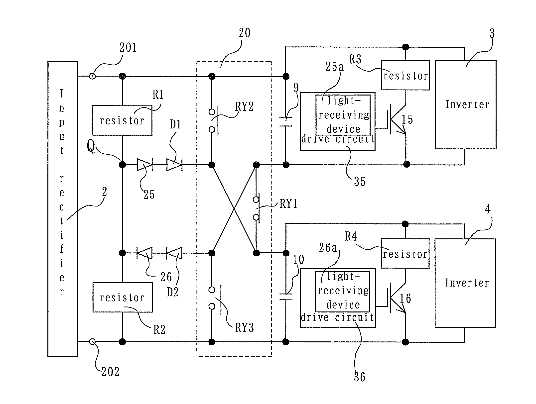
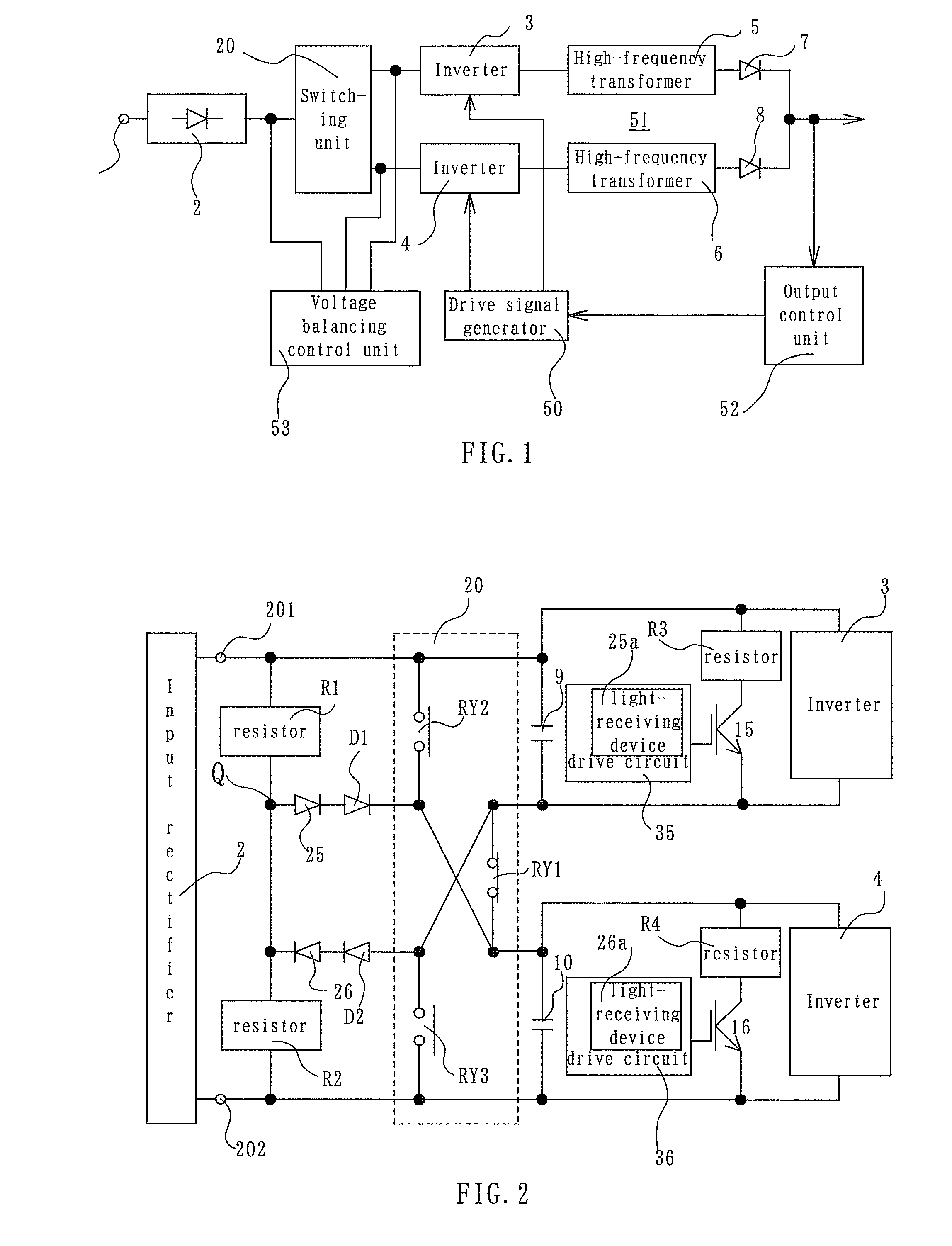
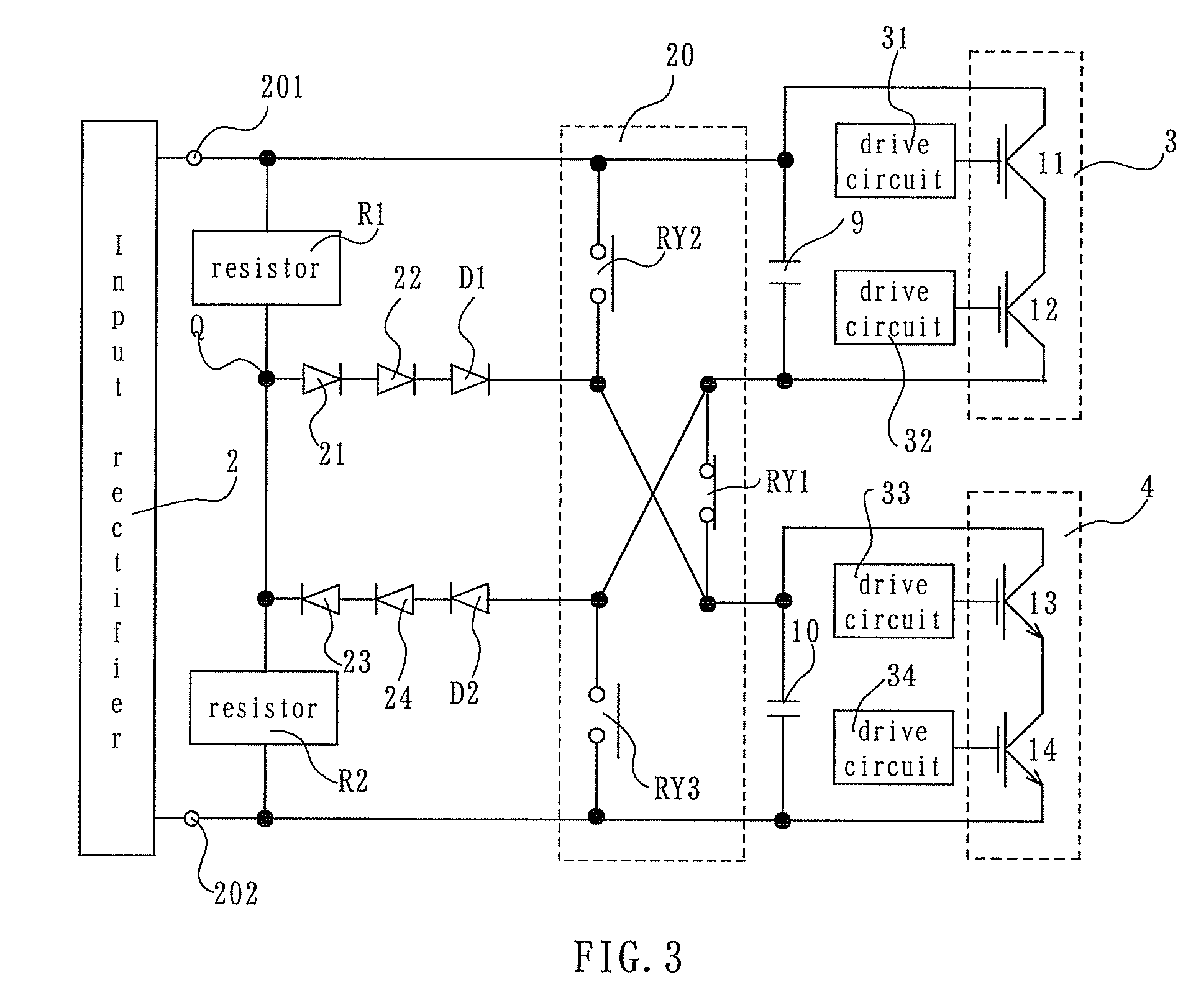
[0017]A power supply apparatus for use with an arc-utilizing apparatus according to one embodiment of the present invention is shown in FIG. 1, and includes an input rectifier 2, which converts an AC input voltage applied to an AC input terminal 1 into a DC voltage. Inverters 3 and 4 are connected in the output side of the input rectifier 2 via a switching unit 20, which is described in greater detail later. A DC voltage from the input rectifier 2 is converted into a high-frequency voltage in each of the inverters 3 and 4. The output high-frequency voltages from the inverters 3 and 4 are voltage-transformed to voltages having a predetermined value in high-frequency transformers 5 and 6, respectively. The high-frequency voltages are rectified by output rectifiers 7 and 8 for application to a load (not shown).

[0018]A selected one of two different valued AC voltages is applied to the AC input terminal 1. A first one of the two AC input voltages is a lower voltage of, for example, about...


PUM

PropertyMeasurementUnit
voltageaaaaaaaaaa
voltageaaaaaaaaaa
AC voltageaaaaaaaaaa

Abstract

An input rectifier of a power supply apparatus rectifies a selected one of two, higher and lower AC voltages applied to it. First and second inverters are connected in the output of the input rectifier. A high-frequency transformer is connected to the output of each of the first and second inverters. An output rectifier is connected to the output of each of the high-frequency transformers. When the higher one of the two AC input voltages is applied to the input rectifier, a switching circuit connects the first and second inverters in series between output terminals of the input rectifier. When the lower AC voltage is applied to the input rectifier, the switching circuit connects the first and second inverters in parallel between the output terminals of the input rectifier. When the first and second inverters are connected in series between the output terminals of the input rectifier, a voltage balancing control unit operates to suppress imbalance between input voltages to the first and second inverters.

Description

[0001]This invention relates to a power supply apparatus for arc-utilizing apparatuses, such as an arc welder, an arc cutter, and an arch discharge lamp, and, more particularly, to such a power supply apparatus which can be operated from either one of two different valued voltages.BACKGROUND OF THE INVENTION[0002]Conventional small-sized, light-weighted power supply apparatuses for arc-utilizing apparatuses are arranged such that an AC input voltage applied thereto is converted into a DC voltage by an input rectifier. The resultant DC voltage is then converted into a high-frequency voltage by an inverter. The high-frequency voltage is then voltage-transformed to a voltage having a desired value by a high-frequency transformer. The voltage-transformed high-frequency voltage is converted back into a DC voltage by an output rectifier, which DC voltage can be applied to a load. Japanese Patent Application Publication No. HEI 05-277731 A discloses an example of a power supply apparatus f...

Claims


Application Information

Patent Timeline
Patent Type & Authority Patents(United States)
IPC IPC(8): B23K9/10H02M3/24H02H7/10B23K9/073B23K9/09H02M1/10H02M7/12
CPCH02M1/10B23K9/073B23K9/09B23K9/1056B23K9/32H02M7/12
Inventor ISHII, HIDEOIKEDA, TETSURODANJO, KENZOIKEJIRI, YUJI
Owner SANSHA ELECTRIC MFG
Why Eureka
Try Eureka