Airborne weather radar system and radar display

a weather radar and radar display technology, applied in the direction of instruments, navigation instruments, climate sustainability, etc., can solve the problems of not being able to achieve the maximum potential of weather radar, affecting the safety of pilots,

Active Publication Date: 2006-09-19
ROCKWELL COLLINS INC
View PDF29 Cites 206 Cited by
  • Summary
  • Abstract
  • Description
  • Claims
  • Application Information

AI Technical Summary

Benefits of technology

[0010]The hazardous weather conditions are identified using radar reflection data in combination with atmospheric data for determining weather and hazard conditions. A weather radar beam is employed to generate radar reflections from a thunderstorm. In the preferred embodiment the ambient temperature outside the aircraft and aircraft altitude are measured with onboard sensors. The ambient temperature and other atmospheric data are then used to calculate key parameters such as the freezing altitude and tropopause levels. The radar reflections are then analyzed in view of these parameters and iconal representations generated to enhance the radar image and accentuate potentially hazardous conditions and symbolic icons generated when the

Problems solved by technology

It takes training and experience to do this effectively and can represent a substantial workload to pilots who are often busy performing other essential tasks.
Consequently, weather radar may not be used to its maximum potential and hazardous conditions may sometimes be missed.
Howev

Method used


Image

  • Airborne weather radar system and radar display
  • Airborne weather radar system and radar display
  • Airborne weather radar system and radar display

Examples


Embodiment Construction

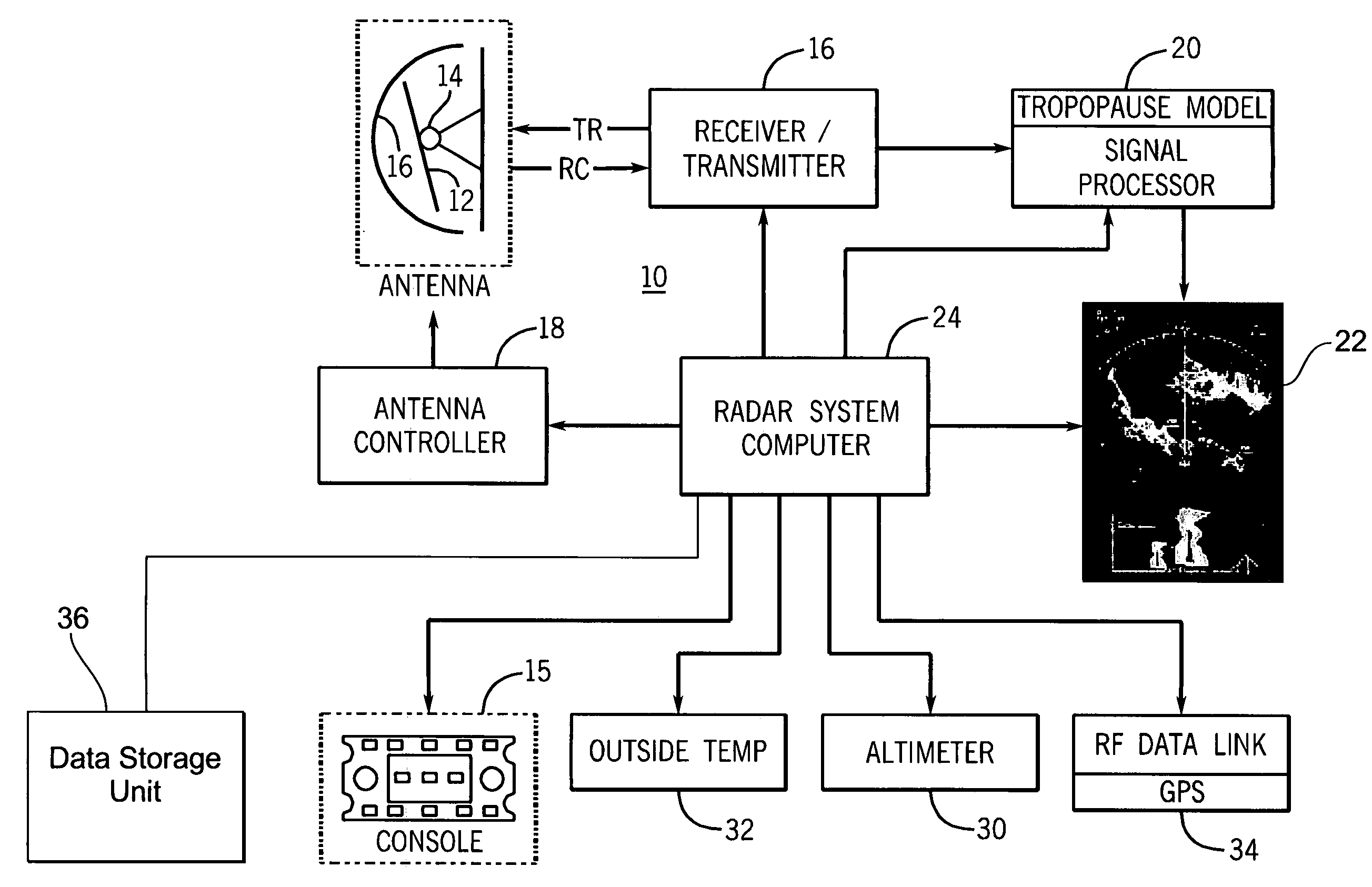
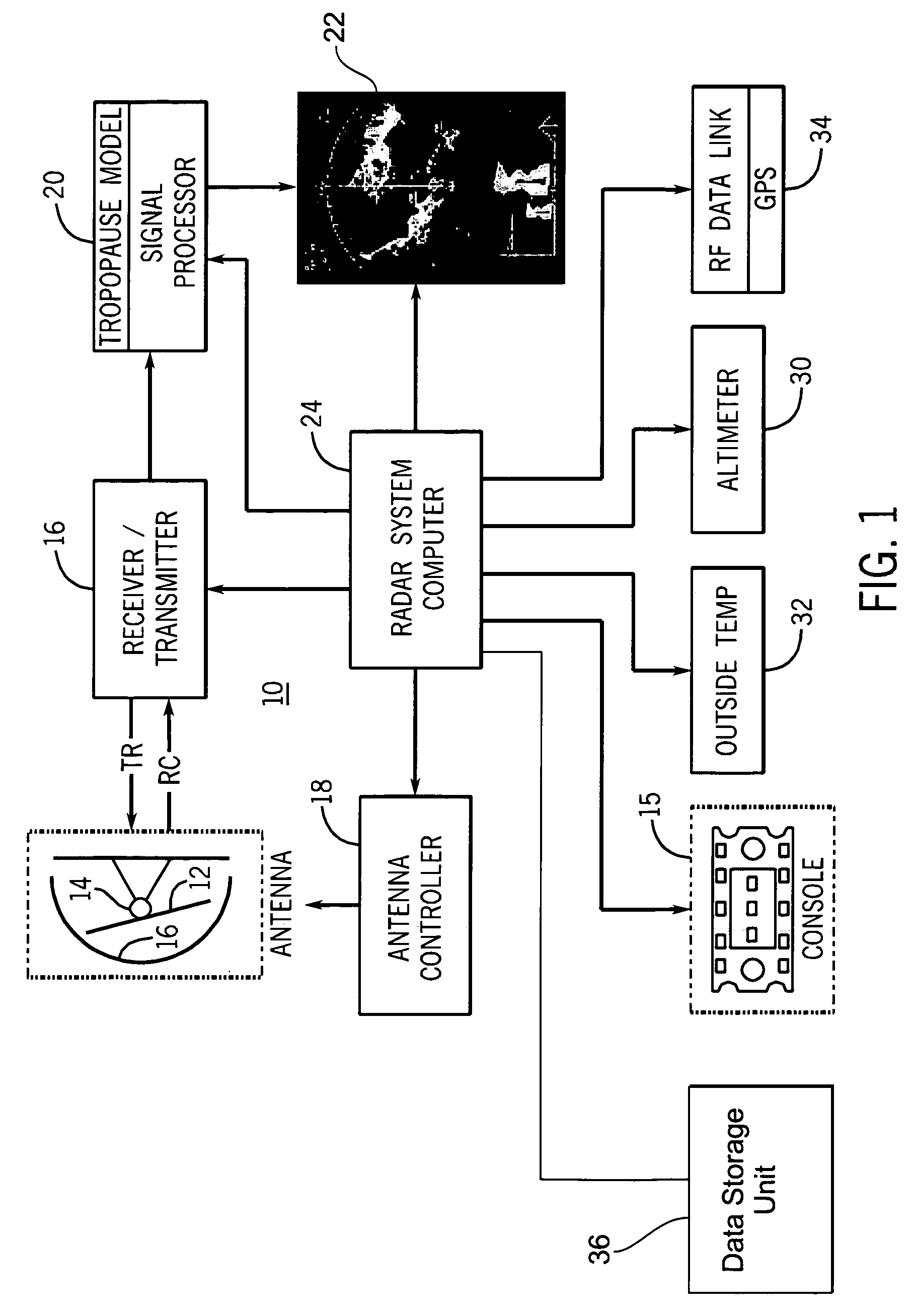
[0024]Referring now to FIG. 1 a block diagram of a weather radar system 10 is shown. The weather radar system 10 includes an antenna 12 mounted on a gimbel 14 within a radome 16. The gimbal 14 enables the antenna 12 to scan throughout a range of azimuth and elevation or tilt angles when in operation at the direction of the antenna controller 18. The system 10 also includes a transmitter / receiver 16 for generating radar signals for supply to the antenna 12 and for amplifying radar signal reflections received from the antenna 12. A signal processor 20 is used for processing the received radar signals into weather information and images and a display screen 22 is used for displaying the images and weather information. The signal processor 20 also preferably includes weather forecasting and storm cell growth and decay prediction algorithms. A microprocessor system or computer 24 controls the weather radar system 10 including the antenna controller 18. Operator input to the computer 24 f...


PUM


Abstract

An airborne weather radar system that detects potentially hazardous weather conditions associated with storms and includes a radar display featuring visual indications of these conditions. The radar display includes a vertical situation display having iconal representations and symbolic icons indicative hazardous weather conditions and aviation hazards along the aircraft's flight path not otherwise immediately apparent or shown on standard weather radar displays. The system includes processes for detecting and predicting hazardous weather conditions such as overshooting thunderstorm tops and vaulted thunderstorm energy and serious hazards such as turbulence and hail.

Description

CROSS REFERENCE TO RELATED APPLICATIONS[0001]The present application is related to co-filed application Ser. No. 10 / 838,290 and filed on an even date herewith entitled “WEATHER RADAR HAZARD DETECTION AND DISPLAY SYSTEM AND METHOD” invented by Steve Paramore and Daniel L. Woodell. The co-filed application is incorporated by reference herein in its entirety.FIELD OF THE INVENTION[0002]The present invention relates to airborne weather radar systems and more particularly to airborne radar systems that can detect and provide warnings about hazardous weather and flight conditions.BACKGROUND OF THE INVENTION[0003]Airborne weather radar systems are used to detect the presence of storms and turbulent weather. This is important since weather is a cause or contributing factor in a large number of aircraft accidents. Weather forecasts are useful but airborne weather radar provides invaluable real time input as to local conditions ahead and in the immediate vicinity of the aircraft. Accordingly,...

Claims


Application Information

Patent Timeline
IPC IPC(8): G01S13/95
CPCG01S13/953G01S7/20G01C23/00Y02A90/10
Inventor PARAMORE, STEVEWOODELL, DANIEL L.BARBER, SARAH
Owner ROCKWELL COLLINS INC
Why Eureka
Try Eureka