Method for generating electromagnetic field distributions

a technology of electromagnetic field and distribution method, applied in the field of optical sensors, can solve the problems of light scattering, reduced light passing through the waveguide, and limited material choice for the wave-conducting layer,

Inactive Publication Date: 2006-09-19
OERLIKON TRADING AG TRUEBBACH
View PDF6 Cites 1 Cited by
  • Summary
  • Abstract
  • Description
  • Claims
  • Application Information

AI Technical Summary

Benefits of technology

[0048]This field distribution can be obtained especially with a system whose homogeneous layer on which the grating is positioned, and/or the grating structure may consist of a low-refraction material and in particular of a material whose refractive index is lower than or equal to the refractive index of the substrate. That also makes it evident that the effect here discussed is not based on, nor can it be derived from, that of the waveguide which...

Problems solved by technology

For a given substrate the choice of materials for the wave-conducting layer is therefore limited to high-refraction materials.
Another problem is posed by the fact that the mode propagation and thus the intensity of the field that is available for excitation depends in highly sensitive fashion on the waveguide configuration and possibly existing imperfections.
Even minute impurities cause light scattering and a diminution of the intensity of the light passing through the waveguide.
That effect is integrally propagated over the entire distance of the light path through the waveguide and even in the case of minute impurities and/or defects it can produce incorrect measurements.
Another difficulty is encountered when coupling the light into the waveguide, which can be accomplished through end-face interfacing, prismatic coupling or via a coupler grating.
In all of these it is difficult to ensure constancy in terms of coupling efficiency which, however, should preferably be obtainable for quantitative measurements.
As another problem, the density of the variou...

Method used


Image

  • Method for generating electromagnetic field distributions
  • Method for generating electromagnetic field distributions
  • Method for generating electromagnetic field distributions

Examples


Embodiment Construction

[0057]The following examples describe this invention in detail with reference to the diagrams.

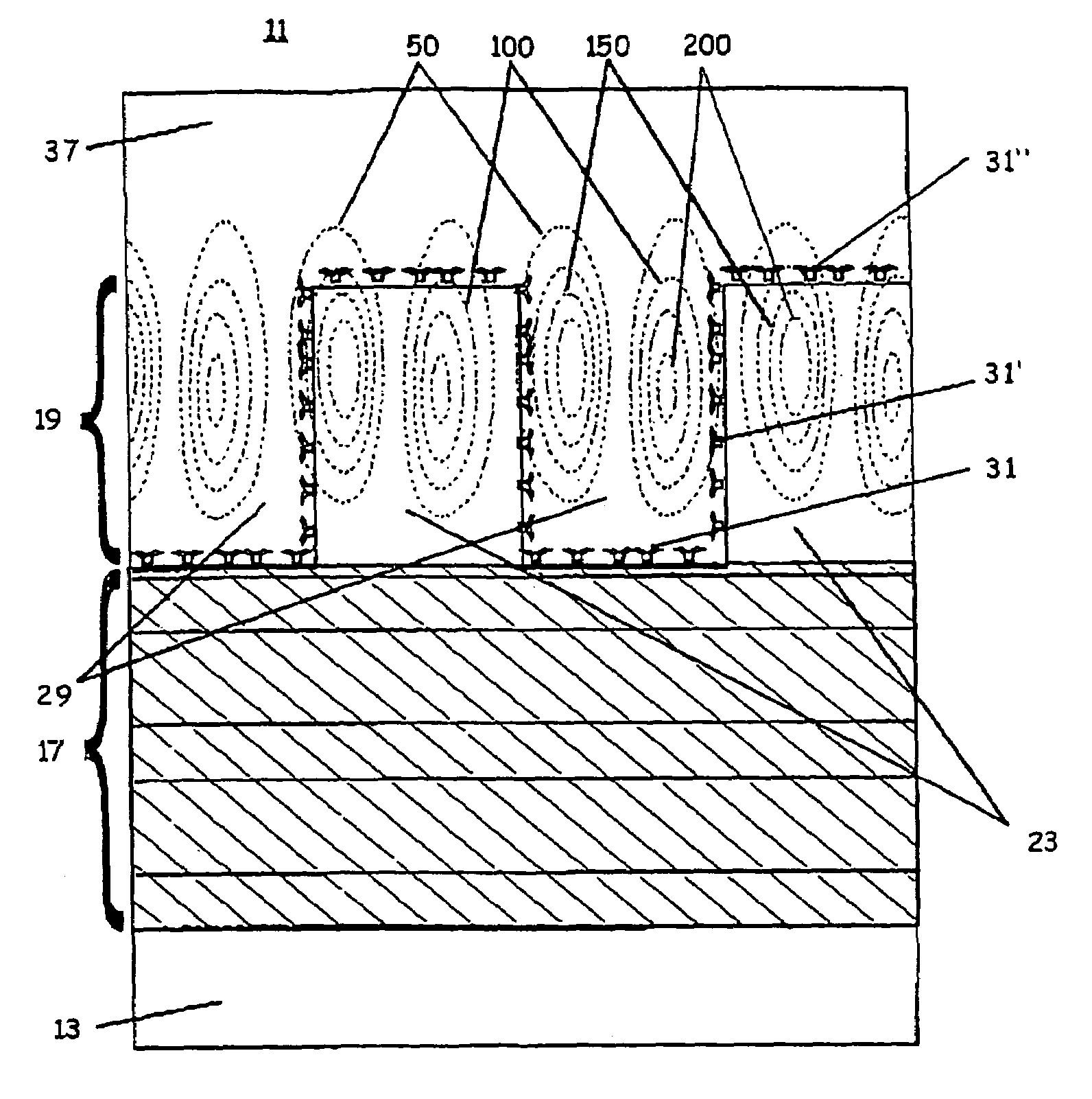
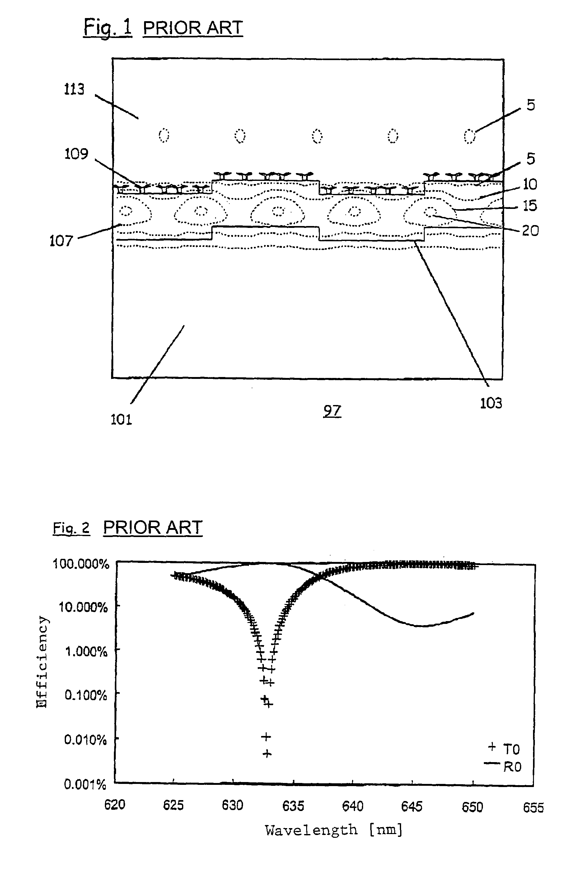
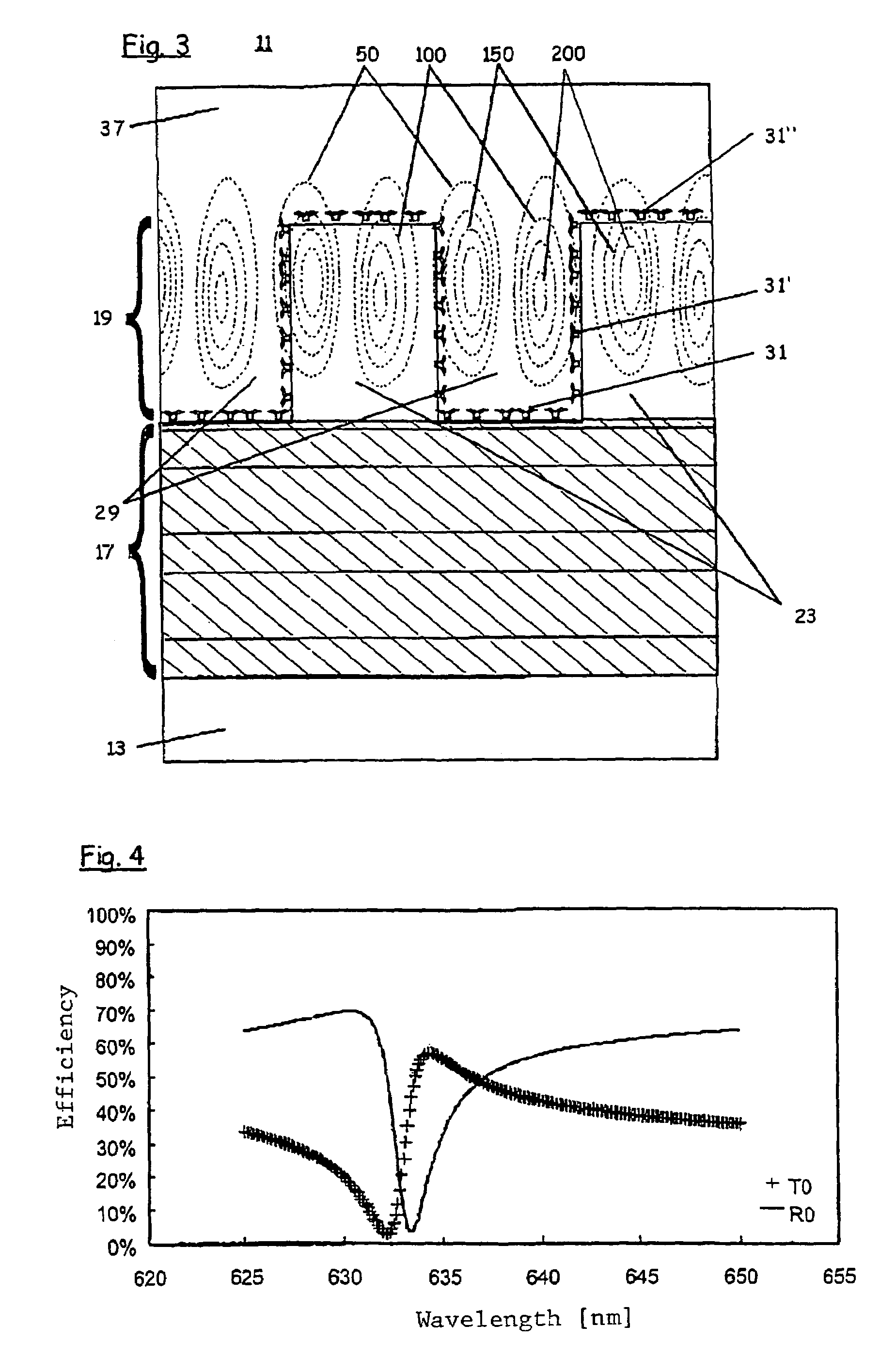
[0058]For a better understanding of the underlying concept of this invention it will be helpful to first analyze in depth a typical prior-art example as disclosed in the Novartis application. That type of system 97 is schematically illustrated in FIG. 1. It comprises a structured substrate 101 with a refractive index of n=1.52 and incorporating a periodic grating with a grating periodicity of 360 nm and a grating depth of 38 nm. The structured substrate 101 is coated with a dielectric layer having a refractive index of n=2.2 and a thickness of 130 nm. The refractive index of that layer is thus significantly higher than that of the substrate. In this case the grating profile of the substrate is carried over to the surface that constitutes the interface with the surrounding medium, hereinafter referred to as the superstrate 113. The drawing also shows biological binder molecules 109 as used f...


PUM


Abstract

This invention relates to a platform (11) and a method for generating electromagnetic field distributions. The invention relates in particular to optical sensors for measuring biological or chemical substances. The platform (11) according to the invention comprises a substrate (13), a structured layer (19) and, positioned between the substrate (13) and the structured layer (19), a multilayer assembly (17), said components being so matched relative to one another that upon appropriate impingement by electromagnetic radiation an electromagnetic field distribution is generated that is at a maximum within the structured layer (19).

Description

BACKGROUND OF THE INVENTION[0001]This invention relates to a system and a method for generating electromagnetic fields in areas accessible to substances to be irradiated. This invention relates in particular to optical sensors for measuring biological or chemical substances.[0002]Electromagnetic fields are utilized in numerous applications for detecting minute concentrations of substances most typically in liquid samples. There are two basic categories of optical sensors designed to detect substance accumulations on the detector surface: Those used for labeled substances (label methodology) and those that function without such labeling (non-label methodology).[0003]Label methodology encompasses, inter alia, a method whereby the substances to be detected are labeled with a fluorescent dye. Examples of commercially available fluorescent dyes include CY5 for an excitation wavelength of 532 nm, and CY3 for an excitation wavelength of around 635 nm.[0004]While such labeling may be select...

Claims


Application Information

Patent Timeline
IPC IPC(8): G02B5/18G01N21/55
CPCG01N21/4788G01N21/6452G01N21/7743G01N21/774G01N21/7746G02B5/18G01N27/00G02B5/00G01N21/55
Inventor THOME-FORSTER, HEIDIHEINE-KEMPKENS, CLAUS
Owner OERLIKON TRADING AG TRUEBBACH
Why Eureka
Try Eureka