Sound system

Active Publication Date: 2006-09-19
FUJITSU GENERAL LTD
View PDF7 Cites 18 Cited by
  • Summary
  • Abstract
  • Description
  • Claims
  • Application Information

AI Technical Summary

Benefits of technology

[0028]Using the above sound system (11), the level of the signal to have addition is attenuated down to the original signal level so that the channel signal level after the addition does not become high

Problems solved by technology

Therefore, the control cannot be adequately conducted using the above conventional output (fader and balance) controlling means, so that the reduction of a certain channel signal adversely affects the program contents occasionally (e.g. the sounds lack a feeling of being in harmony with the images because some sound to be natu

Method used


Image

  • Sound system
  • Sound system
  • Sound system

Examples


Embodiment Construction

[0038]The preferred embodiments of the sound system according to the present invention are described below by reference to those Figures.

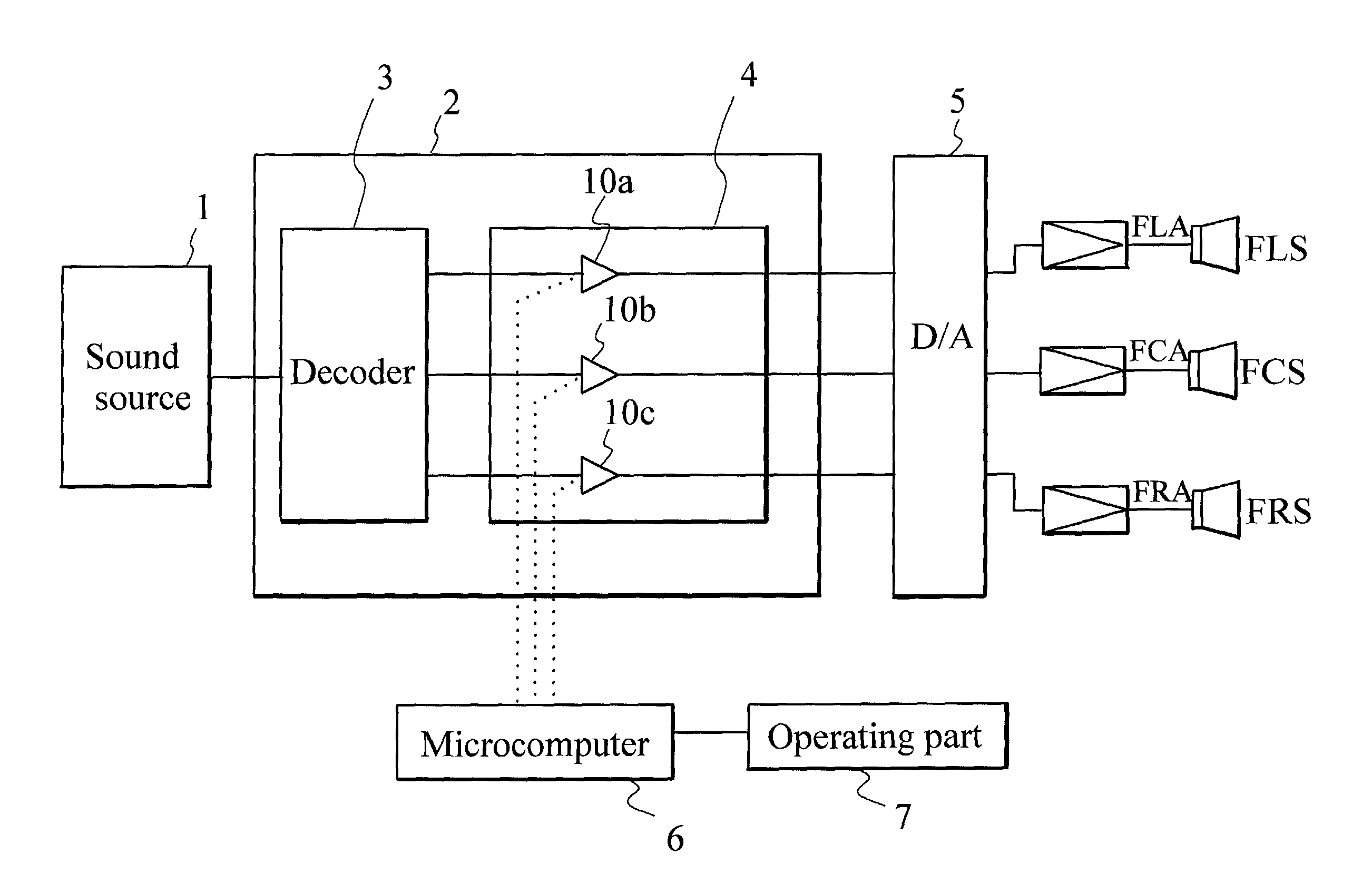
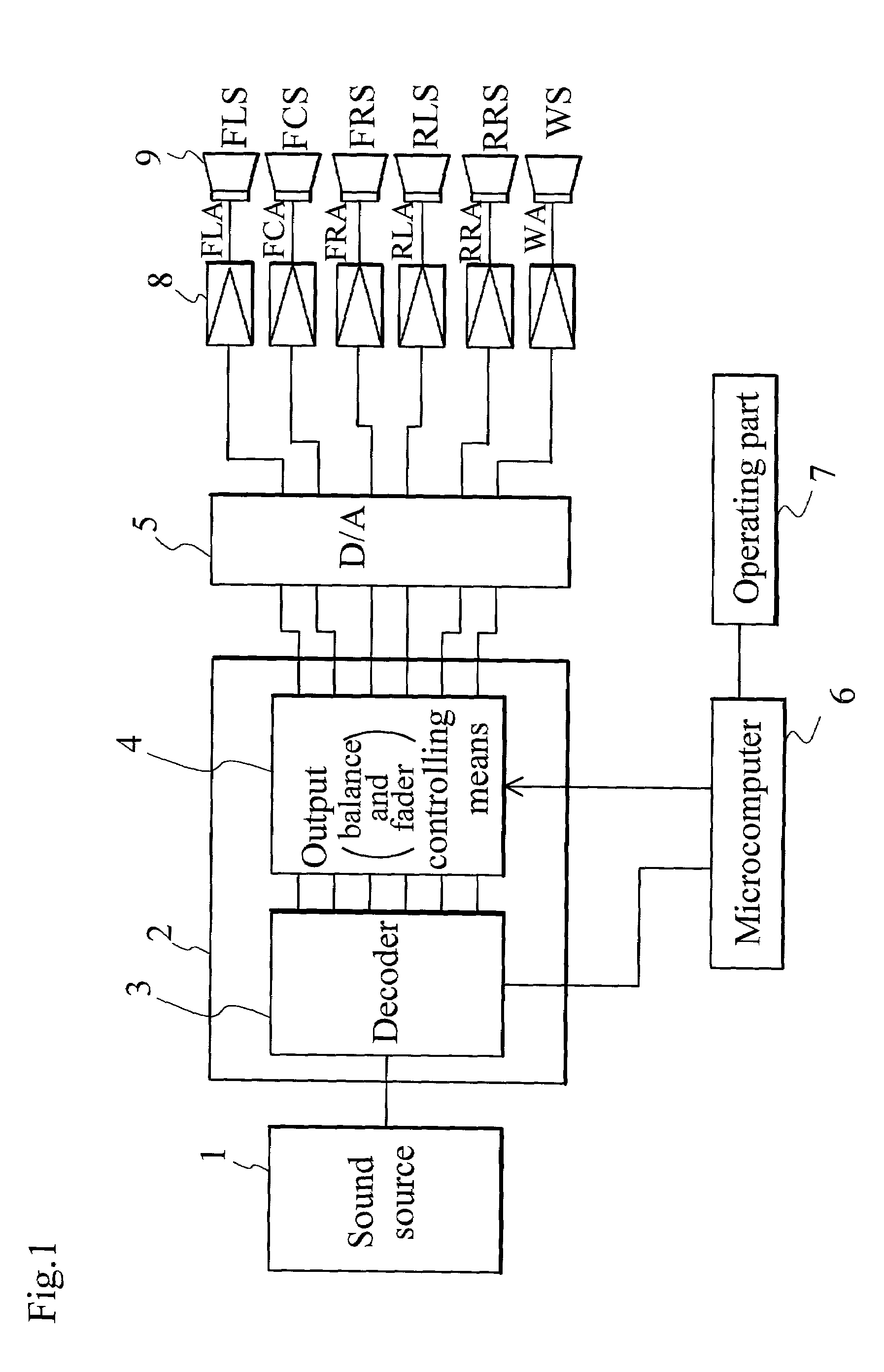
[0039]FIG. 1 is a block diagram showing the construction of a sound system according to an embodiment (1) of the present invention. The sound system according to the embodiment has a sound source 1 such as a DVD, being a multi-track sound source whereby different sounds are output from each speaker arranged in a room, respectively. The sound signals from the sound source 1 are output to a DSP (Digital Signal Processor) 2 which conducts various kinds of digital processing on digital data. The DSP 2 comprises a decoder 3 which decodes digital data from the sound source, and an output balance and fader) controlling means 4 which conducts output control processing on output signals from the decoder 3 based on control signals of output control conditions for each channel from a microcomputer 6 according to how an operating part 7 is operated by a user.

[...


PUM


Abstract

The present invention was developed in order to realize a multi-channel sound system wherein appropriate output (balance and fader) control can be conducted without adversely affecting the program contents, and a sound system, which can reproduce a plurality of channel signals including at least left and right front channels and a center channel for forward-placed speakers, comprises a gain controller to control the gain of either left or right channel signal and a gain controller to control the gain of the center channel signal depending on the gain control of the left or right channel signal.

Description

BACKGROUND OF THE INVENTION[0001]1. Field of the Invention[0002]The present invention relates to a sound system and, more particularly, to a sound system which reproduces a plurality of different channel signals, comprising an output (fader and balance) controlling means.[0003]2. Description of the Relevant Art[0004]An output controlling means in a conventional 2-channel sound system is used for correction in the case where the displacement of the normal is caused by the arrangement of speakers, the position of a listener, or the like in reproducing each channel signal using the speakers. The gain on the side toward which the normal is shifted is made smaller thereby, while that on the other side is kept constant. For example, when a control is turned right in left-right balance control, the output level of a channel signal on the right side is constant, while the output level of a channel signal on the opposite left side is attenuated. The sound volume output from the right side sp...

Claims


Application Information

Patent Timeline
IPC IPC(8): H04R5/00H03G3/02H04S3/00H04S7/00
CPCH04S7/30H04S3/00
Inventor MOTOJIMA, AKIRAKOWAKI, HIROSHITOMITA, YUJIMATSUI, HIDEKI
Owner FUJITSU GENERAL LTD
Why Eureka
Try Eureka