Array of fiber optic splicing cassettes

Inactive Publication Date: 2006-09-19
3M INNOVATIVE PROPERTIES CO
View PDF25 Cites 77 Cited by
  • Summary
  • Abstract
  • Description
  • Claims
  • Application Information

AI Technical Summary

Benefits of technology

[0014]In such an arrangement of two pairs of curved slots it is usually necessary to arrange them so that at least two of them cross each other. In order to avoid an undesired movement or blocking of the cassette, a blocking device may be placed into the one of the second slots that in the specific configuration is not used. In another embodiment, blocking device is integrally molded with the cassette, so that it can be easily broken off from the cassette for use as described herein. In one configuration this bloc

Problems solved by technology

This is particularly important since in the telecommunication area to a growing extent data are transmitted besides the pure transmission of voice signals, and interference with or interruption of these signals would be very disadvantageous.
Due to the high number of connections to be established, and the limited number of connections to be made within each cassette, it is necessary to use a large number of these cassettes.
These systems are widely in use but it was recognized that they present some problems.
For example, when choosing a certain cassette to be accessed, a high number of other cassettes must be moved, which as mentioned

Method used


Image

  • Array of fiber optic splicing cassettes
  • Array of fiber optic splicing cassettes
  • Array of fiber optic splicing cassettes

Examples


Example

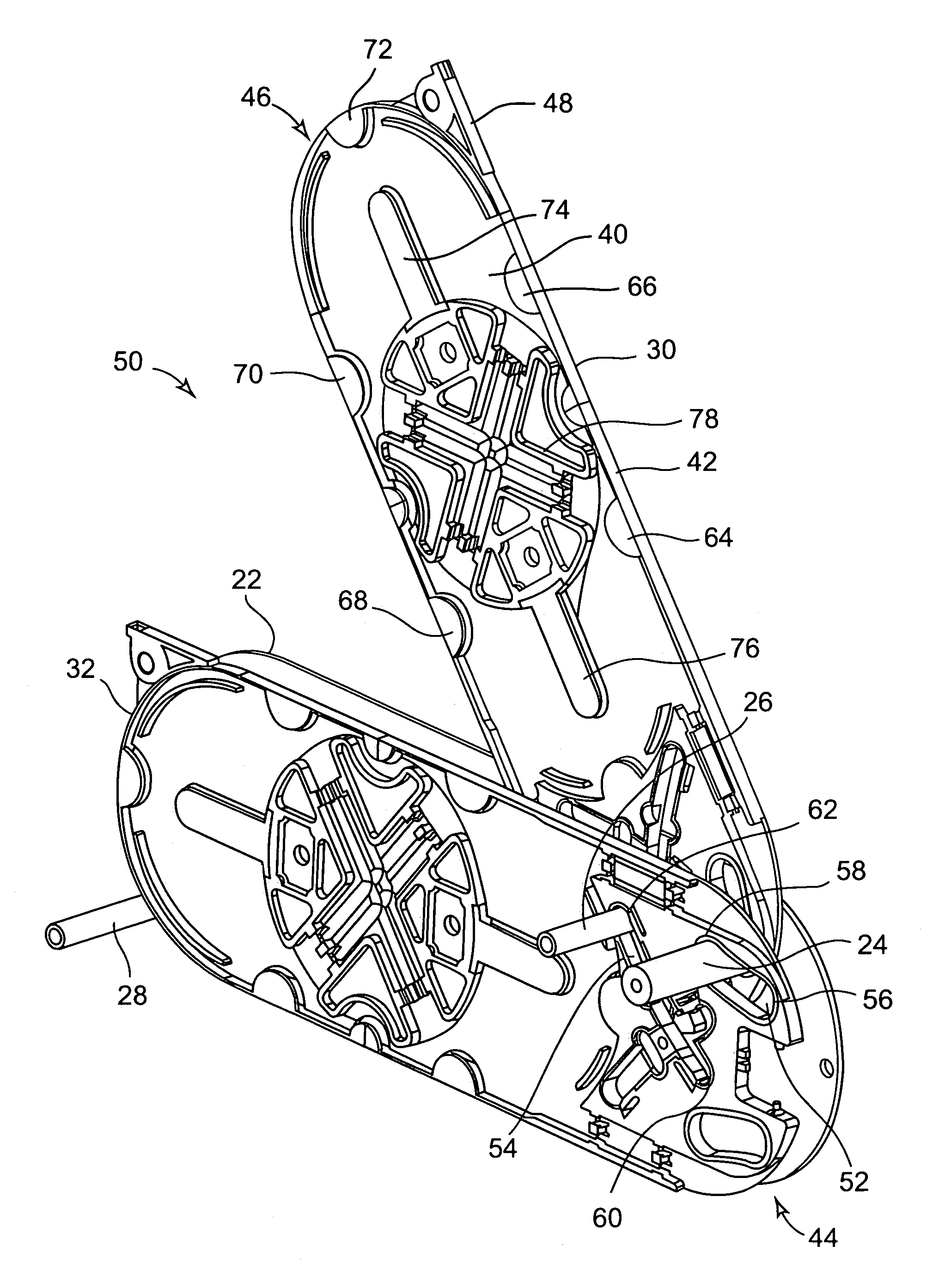
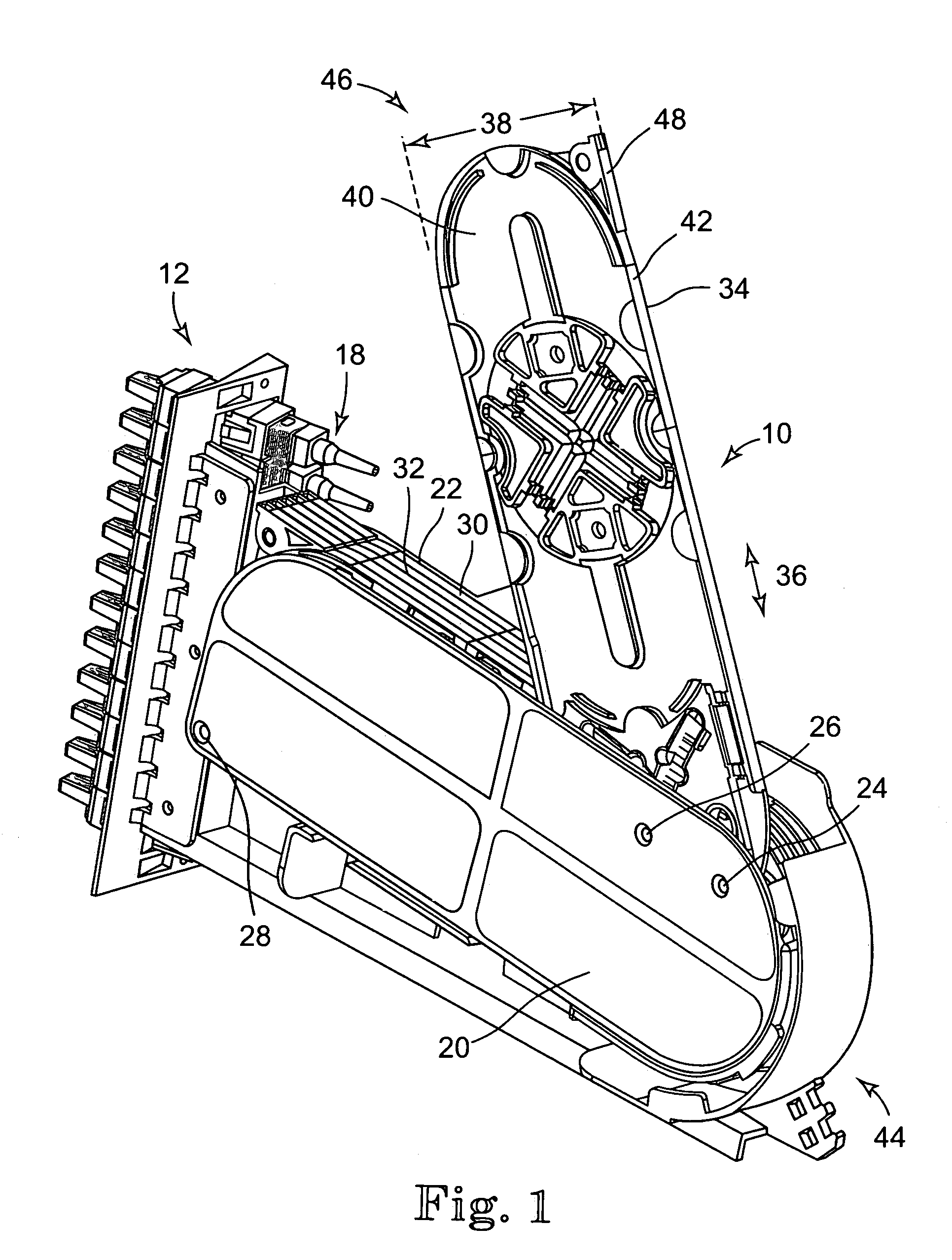
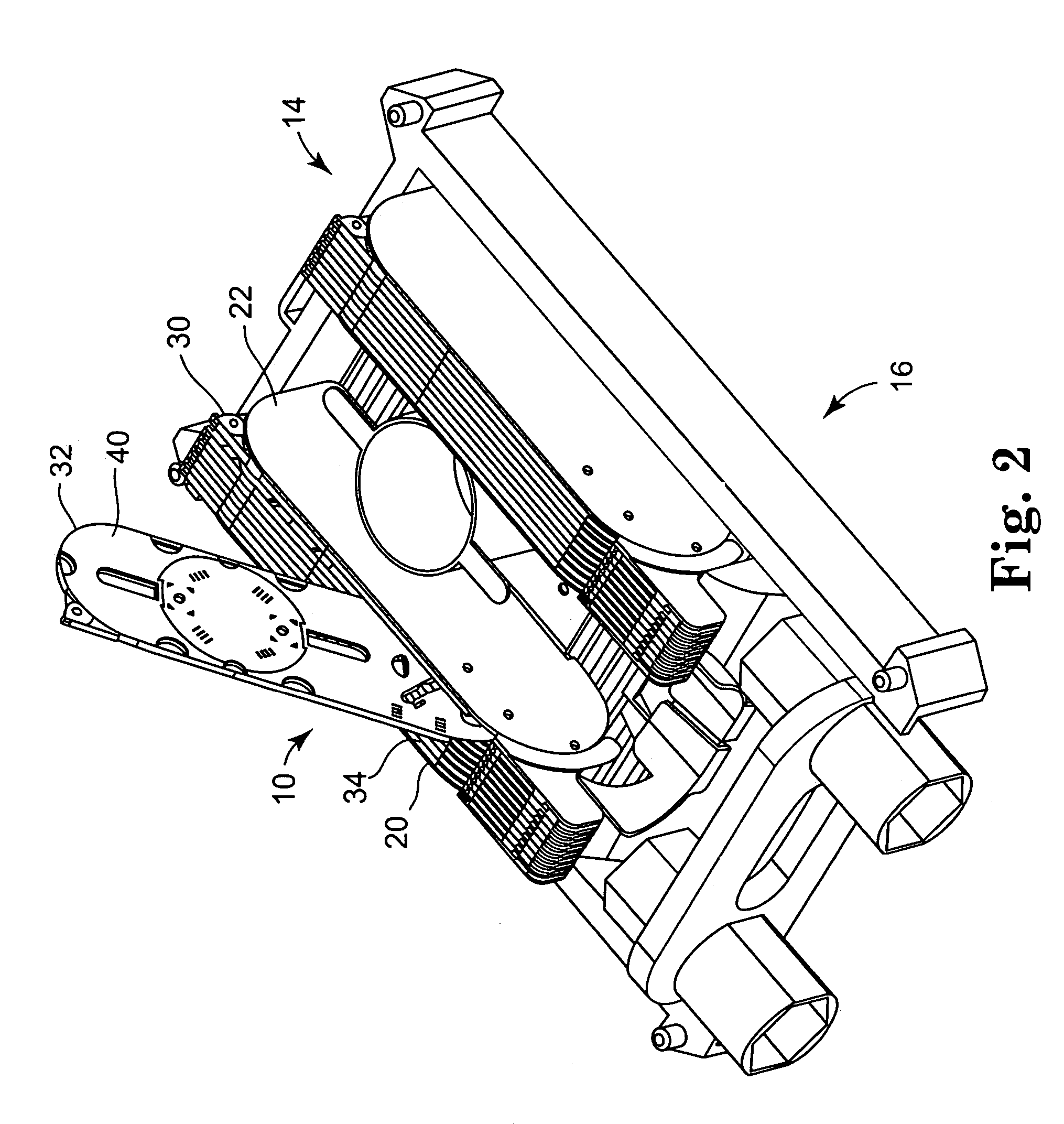
[0030]Arrays of cassettes for the management of optical fibers can be seen in FIGS. 1 and 2. In FIG. 1 the array 10 is mounted into an assembly 12, which is supposed to be placed onto a modular optical distribution frame (MODF) or a 483.6 mm (19 inch) rack or the like. FIG. 2 shows the same array 10 and a second array of the same kind 14 arranged in a common holding device 16 that for example can be part of a splice body for the splicing of two cables containing a multiplicity of optical fibers. FIG. 1 shows on the left side a multiplicity of fiber optic connectors 18, the fibers (not shown) are guided into the array of cassettes 10 to be spliced with incoming fibers. This is generally well known and therefore no further reference will be made to the specific embodiments of the array of cassettes 10, 14 in the environments as shown in FIGS. 1 and 2.

[0031]In the following reference will only be made to the array of cassettes utilizing the same numerals as in FIGS. 1 and 2. The array ...


PUM


Abstract

An array of fiber optic splicing cassettes. The array has first and second side plates connected to one another by first and second axes. The fiber optic splicing cassettes each have a base and first and second curved slots in the base. Each of the first slots is moveably engaged on the first axis, and each of the second slots is moveably engaged on the second axis. In this way each of the cassettes may be moved between an open position and a closed position by simultaneously moving the first and second slots in one of the cassettes relative to the first and second axes.

Description

CROSS-REFERENCE TO RELATED APPLICATION[0001]This application claims priority to U.S. Provisional Patent Application No. 60 / 419,037, filed Oct. 15, 2002 and U.S. Provisional Patent Application No. 60 / 418,149, filed Oct. 11, 2002.TECHNICAL FIELD[0002]The invention relates to a system that allows the management or organization of optical fibers to be used in an optical fiber telecommunication network. It relates more particularly to a system of cassettes allowing the organization of optical fibers including splices. The invention further relates to manufacturing techniques for those cassettes.BACKGROUND OF THE INVENTION[0003]The use of optical fibers has become more and more dominant in the telecommunication field. This results in a growing number of optical fibers to be handled, especially to be spliced and connected and distributed, and therefore systems for the management or organization of optical fibers are used to a growing extent. It is necessary to have an optimum organization ...

Claims


Application Information

Patent Timeline
IPC IPC(8): G02B6/00G02B6/44
CPCG02B6/4455G02B6/44G02B6/46
Inventor DILLAT, MICHEL
Owner 3M INNOVATIVE PROPERTIES CO
Why Eureka
Try Eureka