Digital signal processor computation core with input operand selection from operand bus for dual operations

Inactive Publication Date: 2006-09-19
ANALOG DEVICES INC
View PDF62 Cites 26 Cited by
  • Summary
  • Abstract
  • Description
  • Claims
  • Application Information

AI Technical Summary

Benefits of technology

[0023]According to a further aspect of the invention, a method is provided for executing programmed instructions. The method comprises the steps of executing digital signal processor operations in an execution block in response to digital signal processor instructions configured for efficient digital signal computation, and executing microcontroller operations in the execution block in response to microcontroller instructions configured for code storage density. An application program having a mixture of digital signal processor instructions and microcontroller instructions is characterized by high code storage density and efficient digital signal computation.
[0024]According to another aspect of the invention, a digital signal processor having a pipeline structure is provided. The digital signal processor comprises a computation block for executing computation instructions, the computation block having one or more computation stages of the pipeline structure, and a control block for fetching and decoding the computation instructions and for accessing a memory, the control block having one or more control stages of the pipeline structure. The computation stages and the control stages are positioned in the pipeline structure such that a result of the memory access is available to the computation stages without stalling the computation stages

Problems solved by technology

Digital signal processor applications are typically characterized by real-time operation, high interrupt rates and intensive numeric computations.
In addition, digital signal processor applications tend to be intensive in memory access operations and to r

Method used


Image

  • Digital signal processor computation core with input operand selection from operand bus for dual operations
  • Digital signal processor computation core with input operand selection from operand bus for dual operations
  • Digital signal processor computation core with input operand selection from operand bus for dual operations

Examples


first embodiment

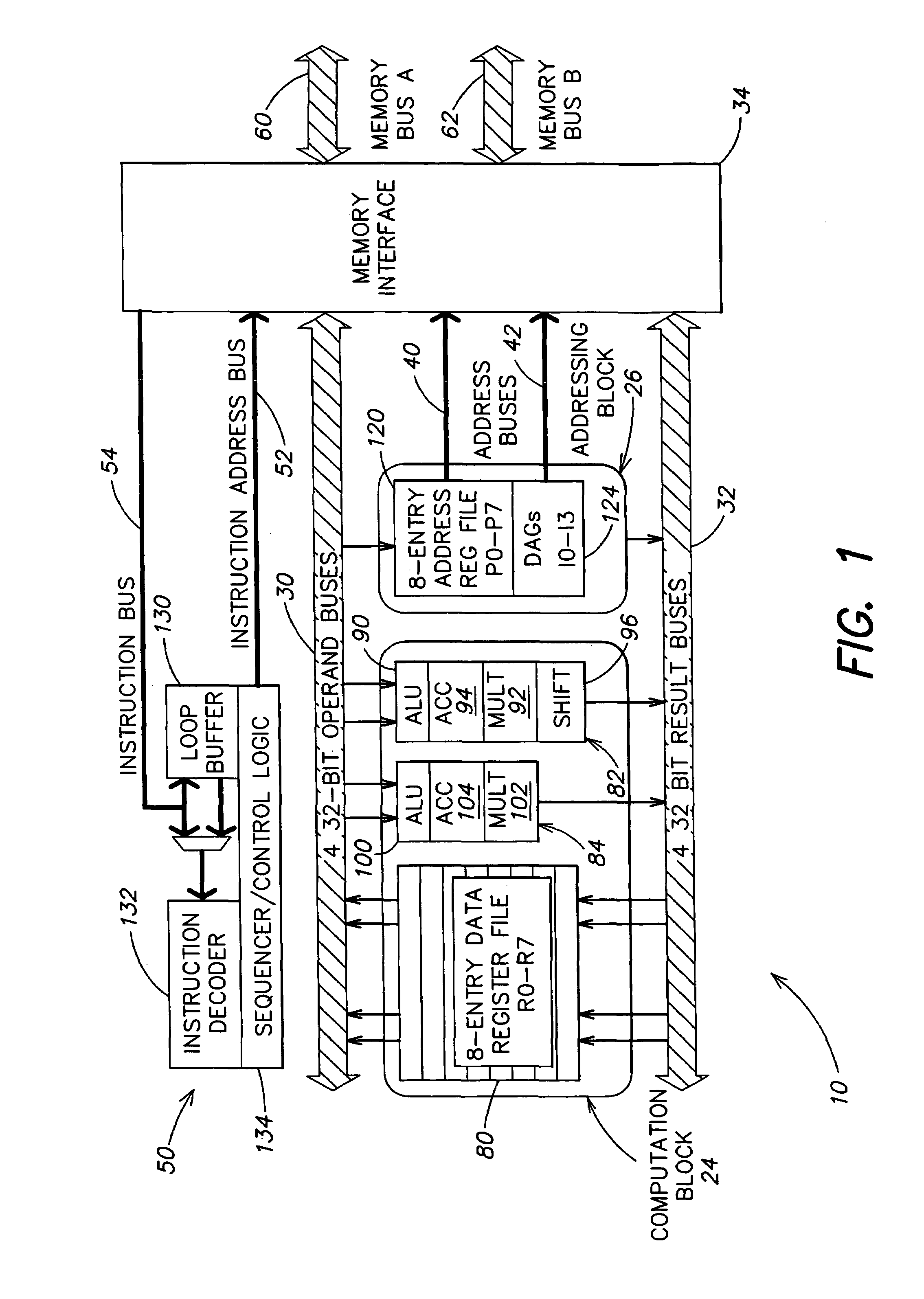
[0056]A block diagram of register file 80, execution units 82 and 84 and memory 64, and the interconnection between these elements, is shown in FIG. 3. In the embodiment of FIG. 3, register file 80 has eight registers and is partitioned into register file banks 200 and 202, each having four registers of 32 bits each. Thus, register file bank 200 contains registers R0–R3, and register file bank 202 contains registers R4–R7. This arrangement results in low power because each four entry register file bank 200, 202 requires less energy per access than a single eight entry register file. Each four entry register file bank 200, 202 requires two read ports and two write ports, while an eight entry register file requires four read ports and four write ports.

[0057]Register file 80 is connected to execution units 82 and 84 and to memory 64 by operand buses 30 and result buses 32. Operand buses 30 include operand bus 210, operand bus 212, operand bus 214 and operand bus 216. Operand buses 210 ...

second embodiment

[0058]A block diagram of register file 80, execution units 82 and 84 and memory 64, and the interconnection between these elements, is shown in FIG. 3A. Like elements in FIGS. 3 and 3A have the same reference numerals. In the embodiment of FIG. 3A, register file 80 has a single register file bank 240 having eight registers, R0–R7, of 32 bits each. Register file bank 240 has four read ports and four write ports.

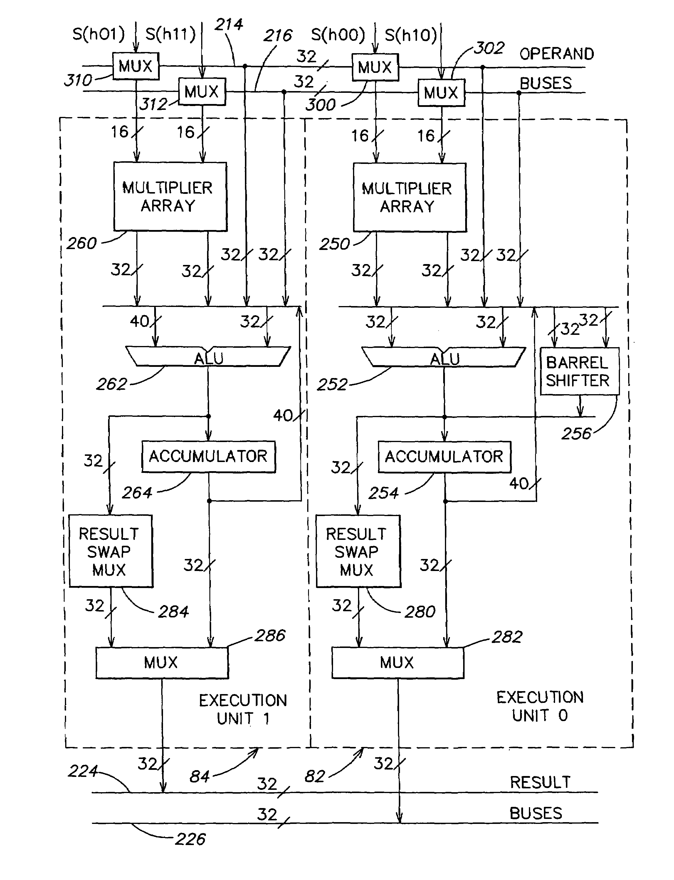
[0059]A block diagram of execution units 82 and 84 is shown in FIG. 4. A portion of execution unit 82 is shown in more detail in FIG. 4A. Execution unit 82 includes a multiplier array 250, an ALU 252, an accumulator 254 and a barrel shifter 256. Execution unit 84 includes a multiplier array 260, an ALU 262 and an accumulator 264. Each multiplier array 250, 260 receives two 16-bit operands and provides two 32-bit outputs to the respective ALUs 252, 262. ALUs 252 and 262 may also receive two 32-bit inputs from operand buses 214 and 216. In a preferred embodiment, ALUs 252 and 26...


PUM


Abstract

A computation core includes a computation block, an addressing block and an instruction sequencer, which are coupled to a memory through a memory interface. The computation block includes a register file and dual execution units. The execution units include features for enhanced performance in executing digital signal computations. The computation core is configured for executing digital signal processor instructions and microcontroller instructions, while achieving efficient digital signal processor computation and high code density. A finite impulse response filter algorithm achieves high performance on the dual execution units.

Description

CROSS REFERENCE TO RELATED APPLICATION[0001]This application claims the benefit of provisional application Ser. No. 60 / 133,766, filed May 12, 1999, which is hereby incorporated by reference.FIELD OF THE INVENTION[0002]This invention relates to digital signal processors and, more particularly, to digital signal processor computation core architectures that facilitate complex digital signal processing computations.BACKGROUND OF THE INVENTION[0003]A digital signal computer, or digital signal processor (DSP), is a special purpose computer that is designed to optimize performance for digital signal processing applications, such as, for example, Fast Fourier transforms, digital filters, image processing and speech recognition. Digital signal processor applications are typically characterized by real-time operation, high interrupt rates and intensive numeric computations. In addition, digital signal processor applications tend to be intensive in memory access operations and to require the ...

Claims


Application Information

Patent Timeline
IPC IPC(8): G06F7/38
CPCG06F9/30014G06F9/30036G06F9/30112G06F9/3885G06F9/30149G06F9/3824G06F9/3867G06F9/3012
Inventor ANDERSON, WILLIAM C.EDMONDSON, JOHNFRIDMAN, JOSEHOFFMAN, MARCRIVIN, RUSSELL L.
Owner ANALOG DEVICES INC
Why Eureka
Try Eureka