
Device for detecting the presence of a chemical contaminant

a technology for detecting the presence of a chemical contaminant and a device, which is applied in the direction of measuring devices, water testing, instruments, etc., can solve the problems of prohibitively high cost of many applications, physical disability or no longer function of many of these devices, and achieve the effect of low cos

Inactive Publication Date: 2006-09-26
MASSTECH INT
View PDF34 Cites 2 Cited by
  • Summary
  • Abstract
  • Description
  • Claims
  • Application Information

AI Technical Summary

Benefits of technology

[0006]The present invention aims to provide a low cost, disposable device which does not require electricity.
[0009]The device is based on simple chemistry and therefore cannot fail to work upon contact with the chemical to be detected. The device can be made very simple in construction allowing it to be produced very cheaply.
[0012]With the second aspect of the invention, as the failure element is elongate (for example, the length of the failure element in the direction in which the indicator element moves on failure is at least 3 times, preferably at least 10 times, more preferably at least 20 times, and most preferably at least 50 times its size in any other dimension), it can be extended across a zone in which chemical contaminant is to be detected, thereby providing a cost effective way of detection beyond a single location.
[0018]In an alternative arrangement the indicator element comprises a core surrounded by a sleeve, the sleeve being biased away from the core, wherein the failure element holds the sleeve in a position in which it surrounds the core, whereby, when the failure element fails, the sleeve is released and moved away from the core providing a visual indication of the presence of the contaminant. Preferably, the outer surface of the sleeve is a different color from the outer surface of the core, thereby improving the visual indication of the presence of a contaminant.
[0019]In addition to the provision of visual indication, the device can also be arranged to operate some failsafe mechanism to prevent further contamination, such as by automatically closing a valve.
[0020]In its simplest form, the failure element is made of a single material which fails in the presence of a single contaminant. However, more complex devices are envisaged where the failure element comprises a number of different materials arranged in series and / or in parallel. With different materials arranged in series, the device will operate when any one of a number of contaminants to which a single material is responsive, is present. A parallel arrangement, on the other hand, will only fail when contaminants to which all of the materials are responsive are present. With a combination of series and parallel materials, a device can be tailored to detect a sophisticated selection of contaminants.

Problems solved by technology

Chemical detection devices are frequently electronic and therefore have to be designed to be intrinsically safe making them prohibitively expensive for many applications and are dependent on the reliability of the power supply.
Further, recent surveys in filling stations have shown that many of these devices have been physically disabled or no longer function for other reasons.

Method used


Image

  • Device for detecting the presence of a chemical contaminant
  • Device for detecting the presence of a chemical contaminant
  • Device for detecting the presence of a chemical contaminant

Examples


Embodiment Construction

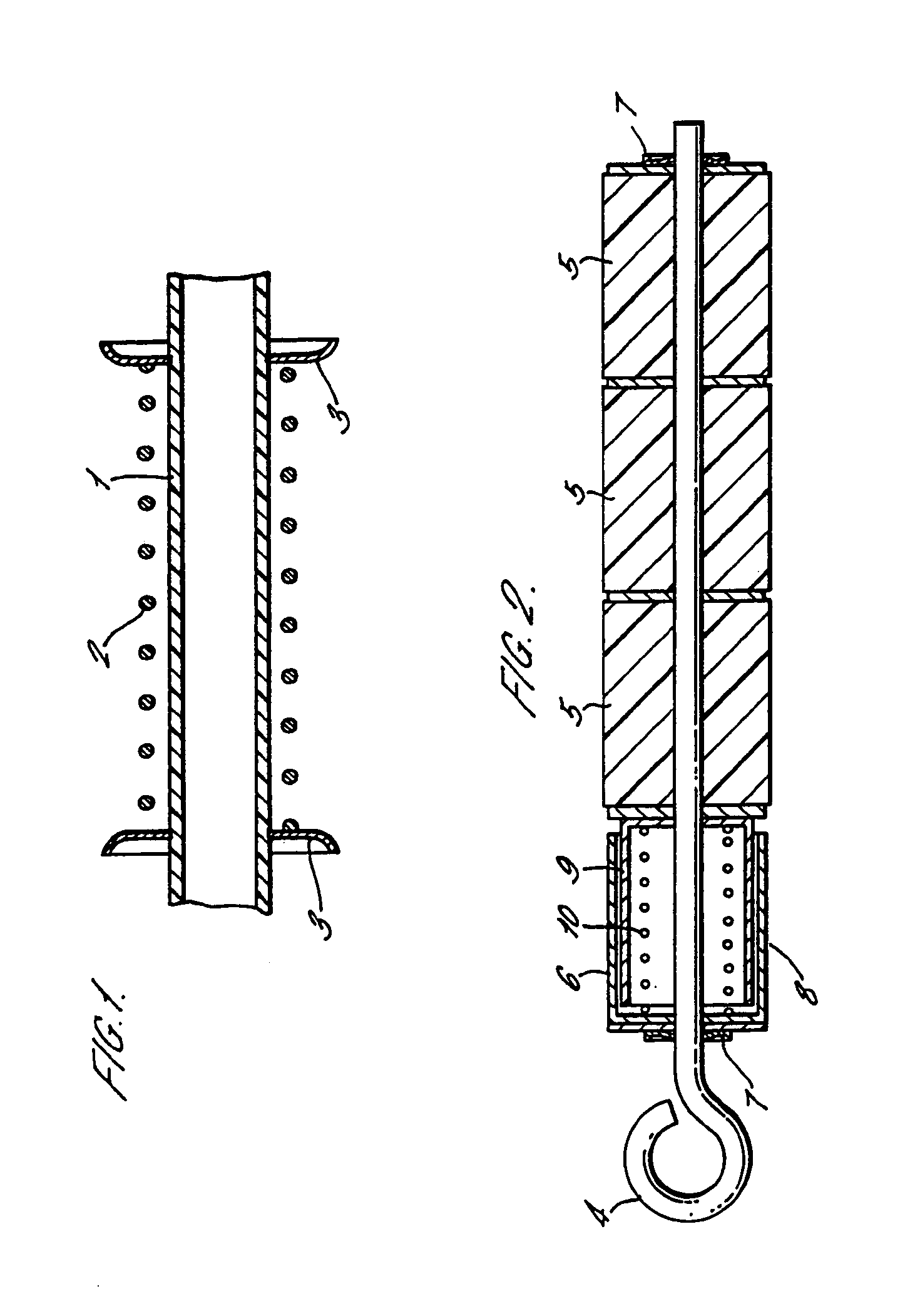
[0031]The device shown in FIG. 1 comprises a tubular member 1 of high-density polystyrene. Attached to the tubular member 1 is a spring 2 which is held in compression by a pair of starlock washers 3 which anchor it to the tubular member 1. In the presence of a chemical contaminant, in this case any petroleum product, the tubular member 1 will fail and the spring 2 extends. The extension of the spring can be used to trigger a mechanical signal or alarm, or can close valves. A cable, such as a bowden cable, may extend through the tubular element and be fixed to one end of the starlock washers. On failure of the tubular member, the cable will be pulled through the tubular element allowing operation of a valve. The failure made may be shearing, stretching or bending of the tubular member, but is more likely to be slippage of a starlock washer when the surface of the tubular member has been degraded by the contaminant.

[0032]A second example is shown in FIG. 2. In this case, the device is...


PUM


Abstract

The disclosure relates to a device for detecting the presence of a chemical contaminant. The device comprising a resilient indicator element which is biased into a first position and is anchored in the first position by means of a failure element. The failure element is made of a material which fails in the presence of a chemical to be detected, thereby releasing the indicator element from its first position and allowing it to move under its own resilience into a second position in order to provide an indication of the presence of the contaminant.

Description

CROSS-REFERENCE TO RELATED APPLICATIONS[0001]This application claims benefit of International Application No. PCT / GB00 / 00959, filed Mar. 15, 2000, and published under PCT Article 21(2) in English, and claims priority of Great Britain Application No. 9906014.7, filed on Mar. 16, 1999. The aforementioned applications are herein incorporated by reference in their entirety.BACKGROUND OF THE INVENTION[0002]1. Field of the Invention[0003]The present invention relates to a device such as an indicator, switch or actuator for detecting the presence of a chemical contaminant. Such a detector is used, for example, in filling stations and chemical plants to detect the presence of unwanted chemicals.[0004]2. Description of the Related Art[0005]Chemical detection devices are frequently electronic and therefore have to be designed to be intrinsically safe making them prohibitively expensive for many applications and are dependent on the reliability of the power supply. Further, recent surveys in f...

Claims


Application Information

Patent Timeline
Patent Type & Authority Patents(United States)
IPC IPC(8): G01D21/00
CPCG01N33/24G01N33/1833
Inventor BRIDGES, ROBERT
Owner MASSTECH INT
Learn More