Rotating damper

a damper and rotating technology, applied in the direction of shock absorbers, elastic bearings, bearing units, etc., can solve the problems of high pressure, heavy weight, and inability to guarantee the durability of the valve body,

Active Publication Date: 2006-09-26
TOK BEARING CO LTD
View PDF7 Cites 18 Cited by
  • Summary
  • Abstract
  • Description
  • Claims
  • Application Information

AI Technical Summary

Benefits of technology

[0012]It is an object of the present invention to provide a rotating damper which is capable of ensuring an adequate rotation angle and has structure causing no damage to any member due to fluid resistance, particularly with use of highly viscous fluid.
[0015]The check valve mechanism in the first and second aspects is capable of being made without a member for holding the valve body provided within the range of relative rotation of the rotating shaft and the casing. As a result, a large rotation angle is ensured. Especially, when highly viscous fluid is used in order for the rotating damper to serve as a high torque damper, if each component inside the casing is increased in thickness enough that no damage is incurred from viscous resistance, it is possible to realize the necessary rotation angle.
[0017]In the above idea, it is possible to adjust timing when the flow limiting mechanism functions in accordance with rotation angle.

Problems solved by technology

However, recent mainstream toilet seats incorporate heaters, and are therefore heavy in weight.
A problem arising in such structure having a valve body repeating bending movement is that the durability of the valve body cannot be guaranteed.
In particular, when the rotating damper is filled with highly viscous fluid to provide higher torque, the valve body is placed under higher pressure, and therefore becomes more susceptible to damage.
Hence, a damper in which the flow passage is adjusted by means of the bending movement of a valve body as described above is inadequate for use as high torque dampers.
As a result, a sufficient rotation angle may not be ensured.
If the rotation angle is insufficient, problems may yet arise, such as the impossibility of retaining the opening state of the cover that stays in a horizontal position in the closing state.

Method used


Image

  • Rotating damper
  • Rotating damper
  • Rotating damper

Examples


first embodiment

[0039]FIGS. 1 to 5 illustrate a rotating damper of a first embodiment according to the present invention.

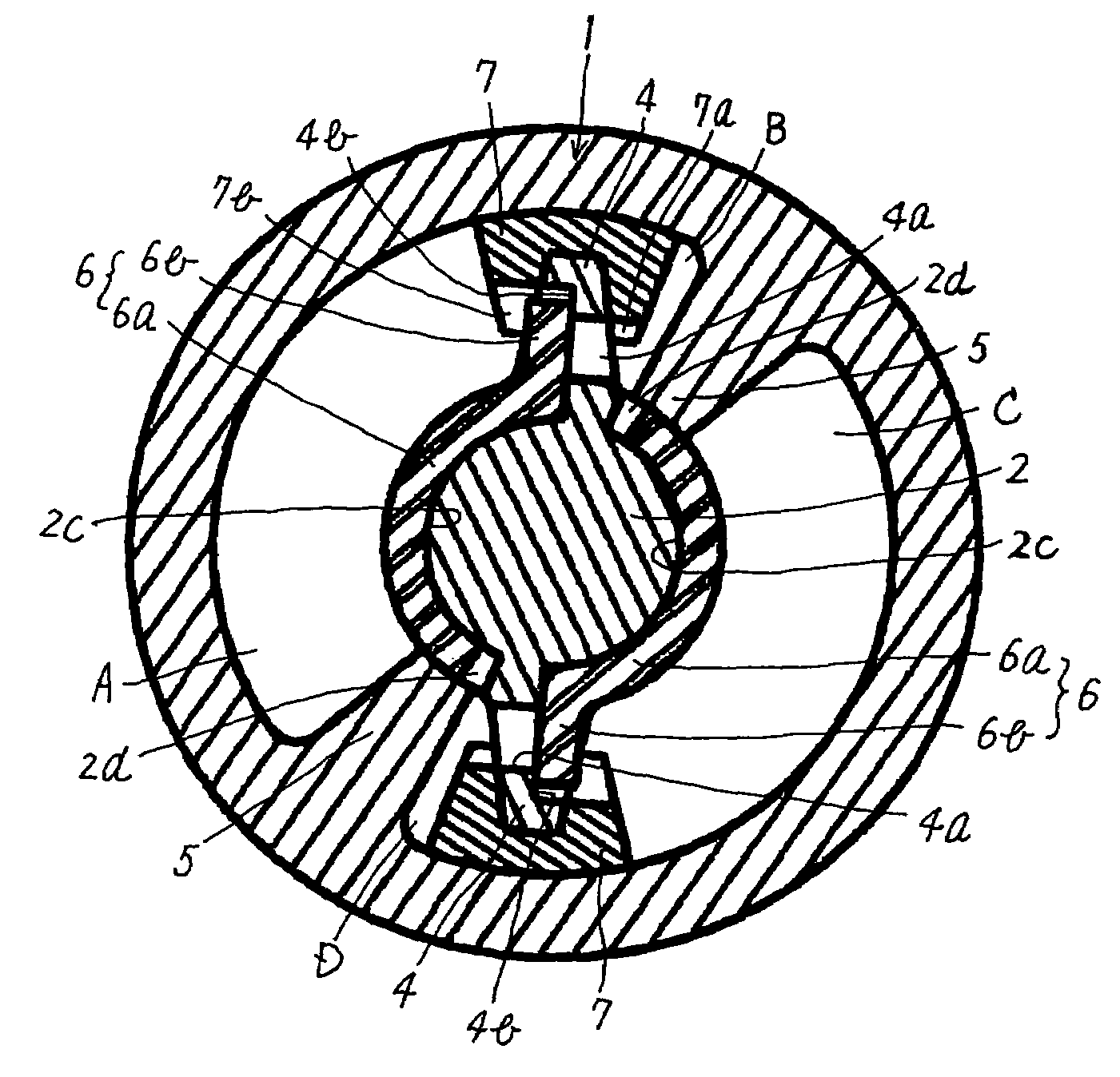
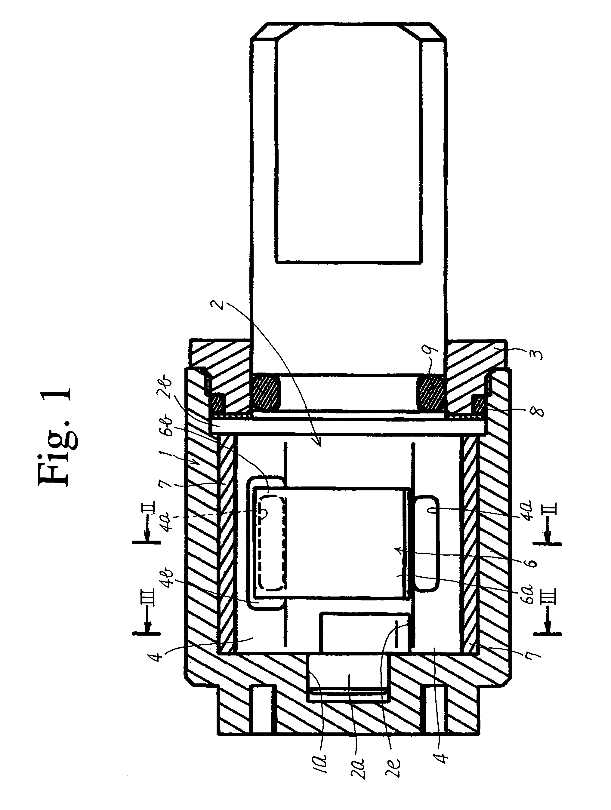
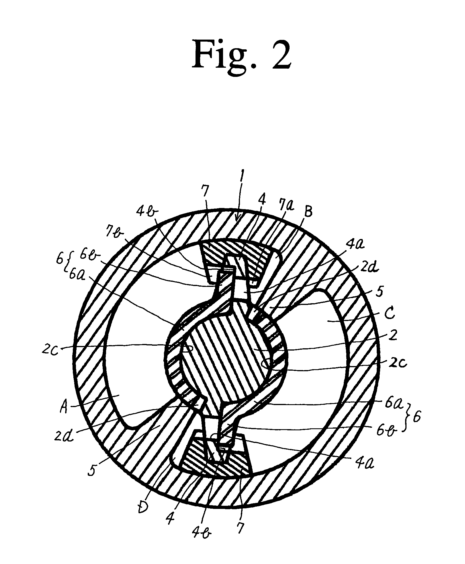
[0040]FIG. 1 is a sectional view along the axis of the rotating damper. FIGS. 2 to 5 are cross-sectional views of the rotating damper in a direction perpendicular to a rotating shaft. Incidentally, FIG. 1 is not a cross section of the rotating shaft 2.

[0041]The rotating damper of the first embodiment includes a cylindrical casing 1 into which a rotating shaft 2 is inserted to allow for relative rotation to the casing 1. An open end of the casing 1 is closed with a cap 3. The rotating shaft 2 has a protrusion 2a formed on a leading end for insertion, and a flange 2b formed in a position back from the leading end for insertion.

[0042]The casing 1 has a recess 1a formed at the other end for receiving the insertion of the protrusion 2a. The protrusion 2a is fitted into the recess 1a and the flange 2b is attached to and fixed by the cap 3, so that the rotating shaft 2 is supported.

[004...


PUM


Abstract

An adequate rotation angle is ensured and any member is not damaged due to fluid resistance even with use of highly viscous fluid. A rotating shaft (2) is provided inside a casing (1) having first divider walls (5) provided on its inner periphery and in direct or indirect contact with the rotating shaft. Second divider walls (4) are provided on an outer periphery of the rotating shaft and in either direct or indirect contact with the casing. A flow passage (4a) is provided in the second divider wall for fluid communication between the pressure chambers. A check valve mechanism has curving portions (6a) moving on and along the periphery of the rotating shaft and valving portions (6b) each joining to the curving portion. The curving portion is supported between the rotating shaft and the first divider wall. The flow passage is opened / closed depending upon a direction of fluid flow.

Description

BACKGROUND OF THE INVENTION[0001]1. Field of the Invention[0002]This invention relates to a damper that rotates to moderate rotational movement of a cover shifting between open and closed positions or the like.[0003]2. Description of Related Art[0004]Rotating dampers having a damping function of reducing rotational speed of piano key covers, toilet seats and the like are known, such as disclosed in Japanese unexamined patent publications No. Hei. 10-211025 (hereinafter referred to as “reference 1”) and No. Hei. 9-280290 (hereinafter referred to as “reference 2”).[0005]The rotating damper, as described in the references, typically includes a rotating shaft provided in a cylindrical casing, divider walls that project from the inner peripheral surface of the casing toward the rotating shaft, and blades that project from the outer peripheral surface of the rotating shaft toward the inner peripheral surface of the casing. A valve body controls fluid flow between pressure chambers each de...

Claims


Application Information

Patent Timeline
Patent Type & Authority Patents(United States)
IPC IPC(8): F16D57/02A47K13/12F16C27/00F16F9/14F16F9/34F16F9/48
CPCF16F9/48F16F9/145
Inventor ORITA, NOBUTOSHI
Owner TOK BEARING CO LTD
Why Eureka
Try Eureka