Light directing structure for a connector

a technology of light directing structure and connector, which is applied in the direction of coupling device connection, lighting and heating apparatus, instruments, etc., can solve the problems of limited application space for designers, insufficient light directing device installation position in the pc, and insufficient brightness of observed light, etc., to achieve the effect of large application spa

Inactive Publication Date: 2006-09-26
LANKOM ELECTRONICS
View PDF3 Cites 5 Cited by
  • Summary
  • Abstract
  • Description
  • Claims
  • Application Information

AI Technical Summary

Benefits of technology

[0006]The primary objective of the present invention is to provide an improved light directing device to enable the light from the LED be redirected to different position from the position where the LED is installed such that the designer has large room available for application.
[0007]Another objective of the present invention is to provide a reflection seat to prevent brightness from loss during light transmission.

Problems solved by technology

However, due to the limitation of the light transmission being linear, the position for installation of the light directing device in the PC is so limited that the designer has little room for application.
Besides, the light from the LED is weakened due to light refraction and scattering effect such that the observed brightness of the light is not as bright as expected.

Method used


Image

  • Light directing structure for a connector
  • Light directing structure for a connector
  • Light directing structure for a connector

Examples


Embodiment Construction

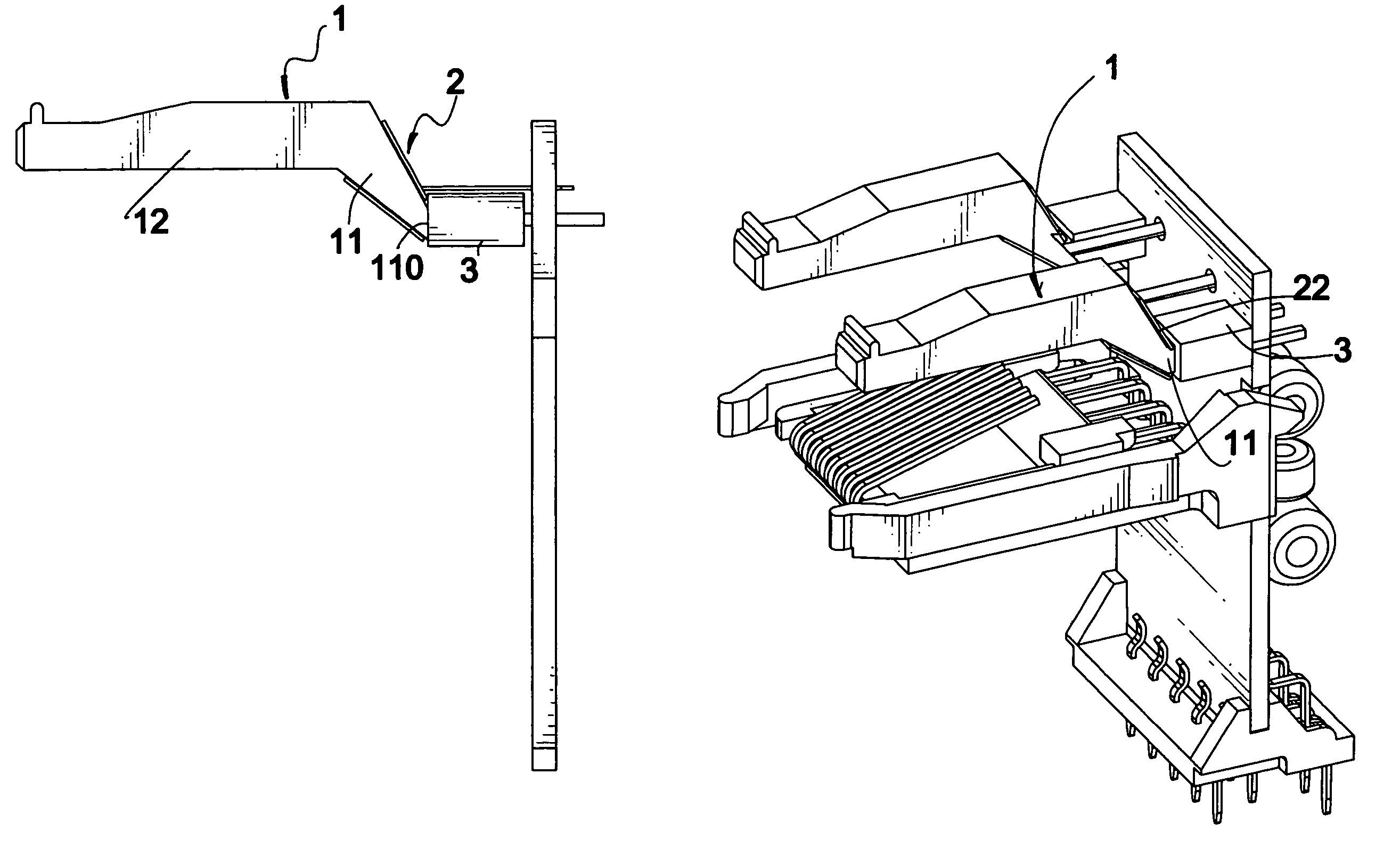
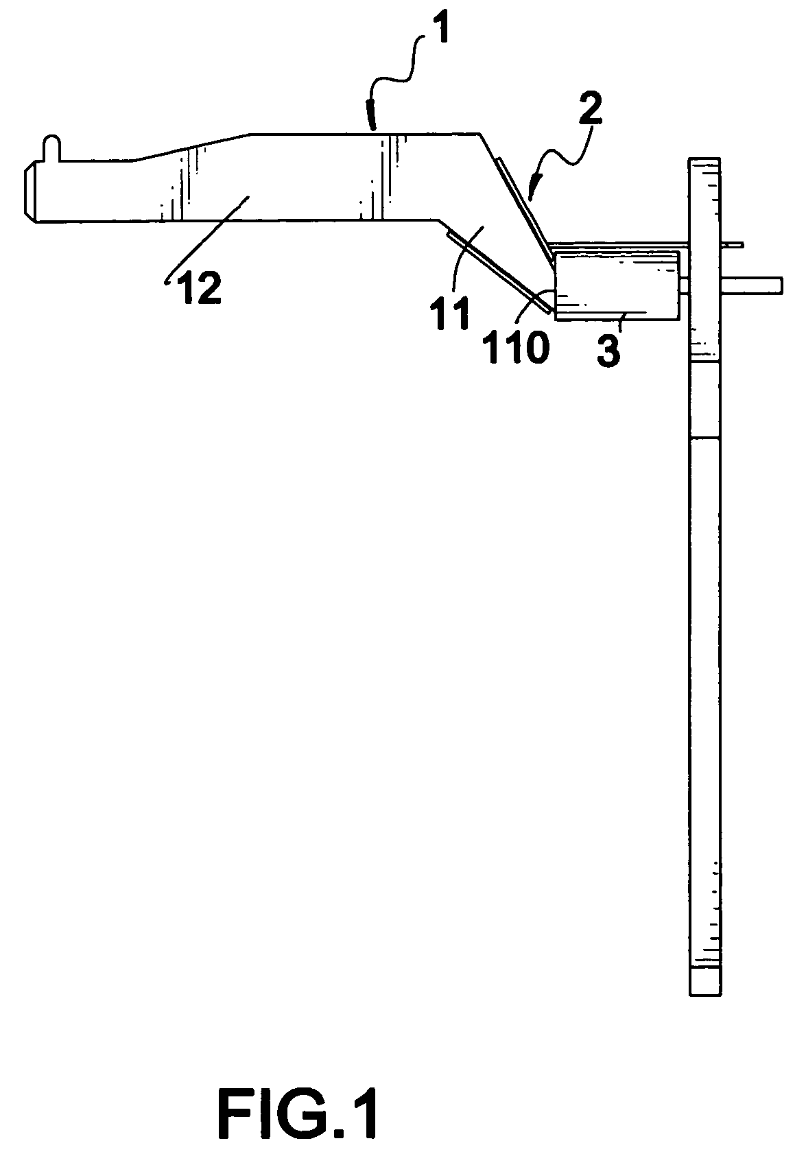
[0016]With reference to FIG. 1, the light directing device in accordance with the present invention includes a translucent tube (1) and a reflection seat (2).

[0017]The translucent tube (1) has a slanted portion (11) and a straight portion (12). The slanted portion (11) has a perpendicular face (110) in parallel to a surface of the light emitting diode (LED) (3).

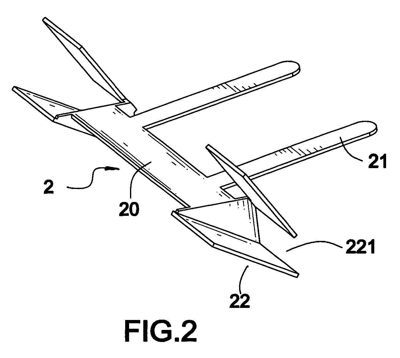
[0018]With reference to FIG. 2, the reflection seat (2) has two extensions (21) extending from the body (20) of the reflection seat (2) and two pairs of covering plates (22) respectively formed on opposite side of the body (20). Each pair of covering plates (22) defines therebetween a gap (221).

[0019]With reference to FIG. 3 and sill considering FIG. 1 as a reference, it is noted that each pair of covering plates (22) is configured in such a way that the slanted portion (11) is able to be fitted between the pair of covering plates (22) and the two covering plates (22) are able to engage with two opposite sides of the slanted ...


PUM


Abstract

A light directing device for a connector includes a translucent tube having a slanted portion and a straight portion. The slanted portion has a perpendicular face adapted to be engaged with a side face of a light emitting diode. A reflection seat is adapted to be securely connected to the connector and having at least one pair of covering plates. Each pair of covering plates defines therebetween a gap for receiving therein the light emitting diode.

Description

BACKGROUND OF THE INVENTION[0001]1. Field of the Invention[0002]The present invention relates to a light directing structure, and more particularly to a light directing structure to redirect the light to different height without loss of brightness.[0003]2. Description of Related Art[0004]A conventional light directing device used in a connector normally includes a straight translucent tube with two ends and a light emitting diode (LED) securely attached to one end of the translucent tube. The other end of the translucent tube is then attached to a surface such that the light from the LED is able to be viewed from the outside of the surface. In general, this kind of light directing device is incorporated with an RJ45 connector which is used in a personal computer for connection with the INTERNET. Therefore, the user is able to observe the connection speed with the INTERNET by the flash of the LED. However, due to the limitation of the light transmission being linear, the position for...

Claims


Application Information

Patent Timeline
Patent Type & Authority Patents(United States)
IPC IPC(8): F21V8/00G02B5/08G02B7/182
CPCG02B6/0008
Inventor LIU, LU-TA
Owner LANKOM ELECTRONICS
Why Eureka
Try Eureka