Automatic position-locking tool carrier apparatus and method

a technology of automatic positioning and carrier apparatus, which is applied in the direction of manufacturing tools, propulsion systems, drilling pipes, etc., can solve the problems of repetitive execution of identical or similar tasks in manufacturing operations, and achieve the effects of low complexity, easy attachment and detachment from workpieces, and light weigh

Active Publication Date: 2006-09-26
THE BOEING CO
View PDF42 Cites 9 Cited by
  • Summary
  • Abstract
  • Description
  • Claims
  • Application Information

AI Technical Summary

Benefits of technology

[0004]The foregoing needs are met, to a great extent, by the present invention, wherein in one aspect a flexible, rail-mounted, automatic position-locking tool-carrying apparatus and method is provided that in some embodiments conforms to a contoured workpiece surface, is relatively light-weight and readily attachable to and detachable from the workpiece, can extend beyond the excursion envelope defined by the rail footprint, and is of relatively low complexity, so as to be relatively inexpensive.

Problems solved by technology

Manufacturing operations frequently require repetitive execution of identical or similar tasks.

Method used


Image

  • Automatic position-locking tool carrier apparatus and method
  • Automatic position-locking tool carrier apparatus and method
  • Automatic position-locking tool carrier apparatus and method

Examples


Embodiment Construction

[0019]An embodiment in accordance with the present invention provides a carriage moveably attached to a flexible rail. A position encoder provides a carriage position signal to a controller, which in response controls a brake mechanism to selectively inhibit or prevent movement of the carriage relative to the rail.

[0020]In addition, a second rail is moveably mounted to the carriage in an orientation perpendicular to the first rail. A second position encoder provides a second rail position signal to the controller, which in response controls a second brake mechanism to selectively inhibit or prevent motion of the second rail relative to the carriage.

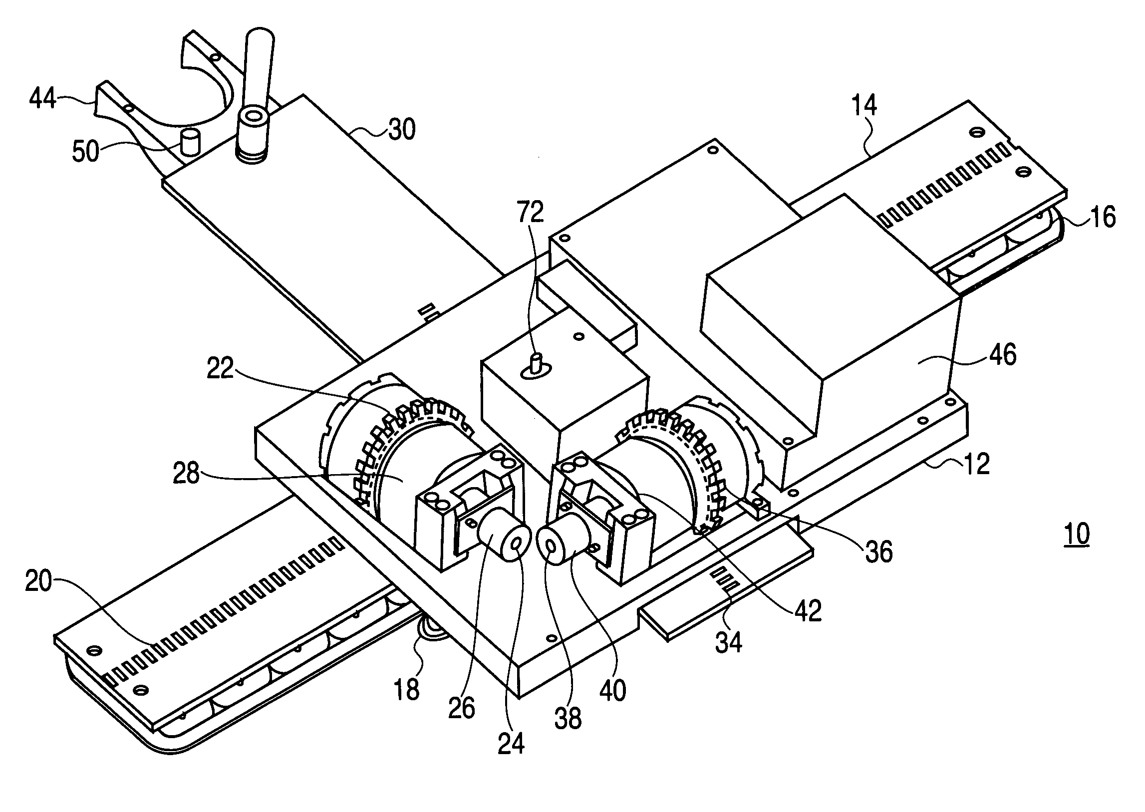
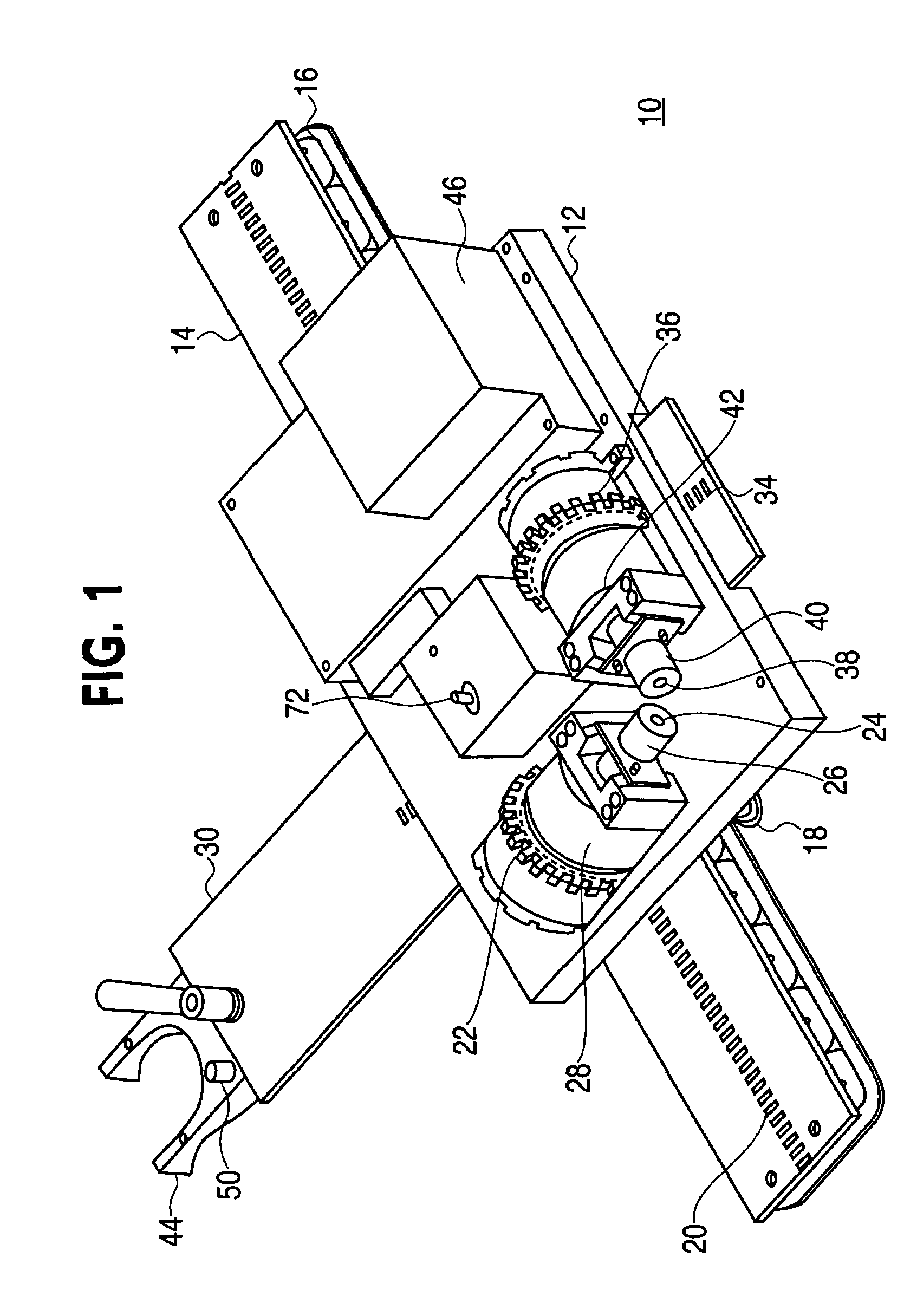
[0021]A preferred embodiment of the invention will now be described with reference to the drawing figures, in which like reference numerals refer to like parts throughout. An embodiment in accordance with the present invention is illustrated in FIG. 1, which shows an automatic position-locking tool carrier apparatus 10. This embodiment in...


PUM

PropertyMeasurementUnit
rotationaaaaaaaaaa
flexibleaaaaaaaaaa
velocityaaaaaaaaaa

Abstract

An automatic position-locking tool carrier apparatus and method include a carriage that rides on a first rail and a second rail translatably connected to the carriage perpendicular to the first rail. Pinion gears that engage with the two rails are attached to the carriage and coupled to position encoders which transmit position signals to a controller. The controller produces control signals to control brake mechanisms coupled to the pinion gears. Translational motion of the carriage and the second rail are limited or prevented when the position of the carriage and the second rail are within predetermined limitations from a predetermined location, fixing the position of an end-effector head attached at one end of the second rail. The carriage and the second rail are propelled by forces external to the system.

Description

FIELD OF THE INVENTION[0001]The present invention relates generally to manufacturing tools and automation. More particularly, the present invention relates to rail-mounted automatic position-locking manufacturing tools and processes.BACKGROUND OF THE INVENTION[0002]Manufacturing operations frequently require repetitive execution of identical or similar tasks. This fact has led to continued efforts to automate manufacturing operations. Much effort has focused on relatively large, stationary automated machines; nevertheless, a need also exists for smaller, lighter-weight, relatively mobile automated manufacturing devices to perform relatively light-duty manufacturing operations.[0003]Accordingly, it is desirable to provide a flexible rail-mounted tool-carrying device that conforms to a contoured workpiece surface, is relatively light-weight and readily attachable to and detachable from the workpiece, can extend beyond the excursion envelope defined by the rail footprint, and is of rel...

Claims


Application Information

Patent Timeline
Patent Type & Authority Patents(United States)
IPC IPC(8): B23C1/20B23B39/00E21B19/00H02K41/00
CPCB23Q9/0042Y10T409/306384Y10T408/554
Inventor BOYL-DAVIS, THEODORE M.OUTOUS, RONALD W.
Owner THE BOEING CO
Why Eureka
Try Eureka