
Load tension alert device

a technology of alert device and load, which is applied in the direction of load securing, flexible elements, transportation items, etc., can solve the problems of decreased strap tension, instability of the truck, injury and damage to property, etc., and achieve the effect of convenient attachmen

Inactive Publication Date: 2006-09-26
TARDIF MAURICE
View PDF5 Cites 54 Cited by
  • Summary
  • Abstract
  • Description
  • Claims
  • Application Information

AI Technical Summary

Benefits of technology

[0005]It is an object of the present invention to provide a tension alert device provided thereby can be easily attached to the securing member.
[0006]It is an advantage of the present invention that the tension alert device can be attached between ends of securing member.

Problems solved by technology

Oftentimes, the accidents are caused by loads shifting on the load bed, which can ultimately cause instability of the truck during turning or when traveling at high speed.
While this type of load securing is satisfactory, it has some significant drawbacks.
For example, loads have a tendency to shift during transport and the tension in the securing members can decrease, which results in unstable loads that may dislodge and fall off the load bed causing injury and damage to property.
Moreover, the vehicle driver is often unaware of this decrease in strap tension and often has to manually check the integrity of the load, especially on long journeys.
This checking increases the delay in delivery of the load and may increase the cost of transporting the load.
However, this device disadvantageously requires attachment of device between one end, i.e. a connecting end, of the securing member and the load bed, thus necessitating use of the link and connector portions and adaptation of the connecting end of member for attachment to device.
This adaptation of member and load bed can be time consuming and cumbersome, and may also engender additional costs.

Method used


Image

  • Load tension alert device
  • Load tension alert device
  • Load tension alert device

Examples


first embodiment

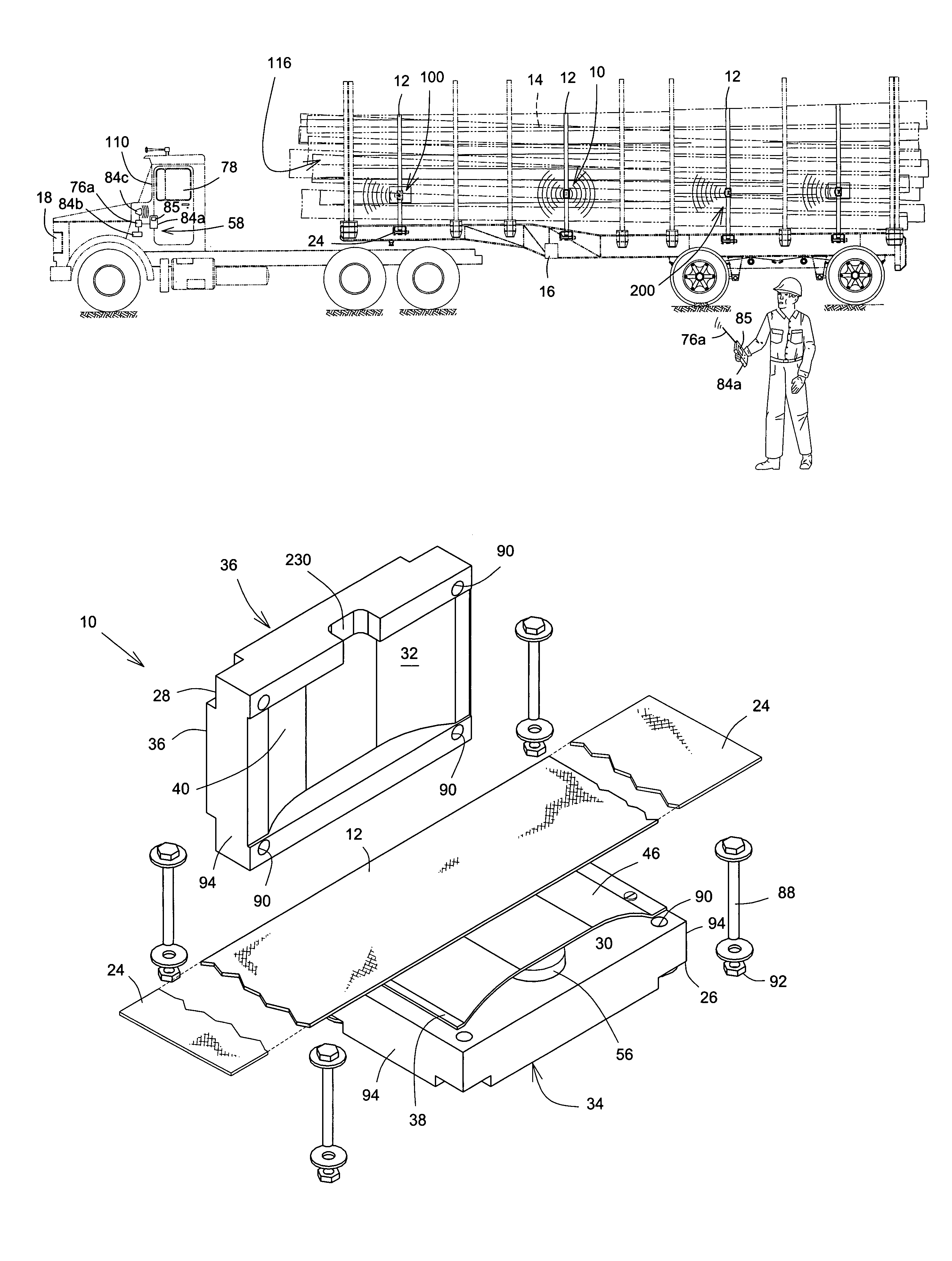
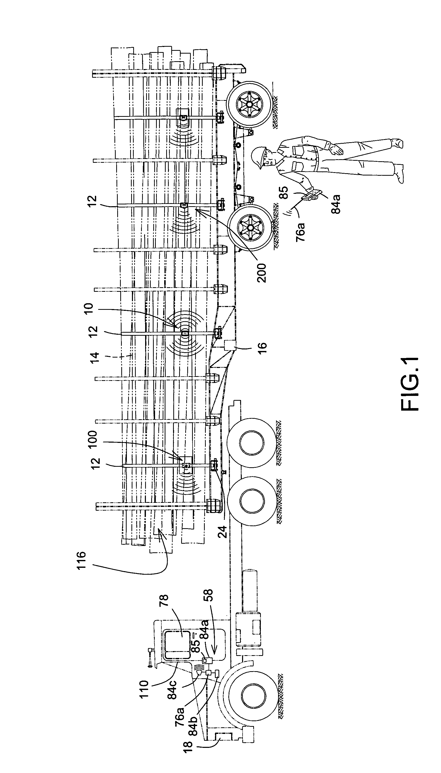
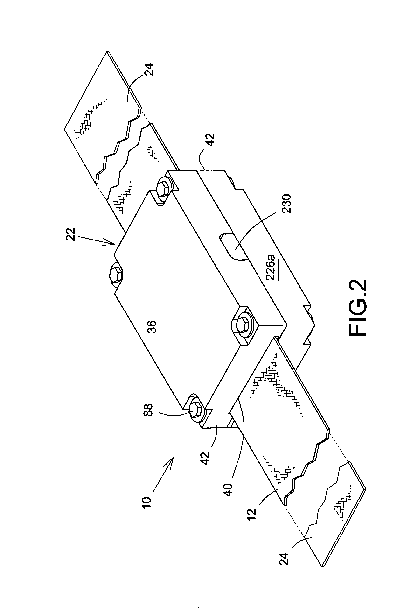
[0024]Referring to FIGS. 1 and 2, tension alert device, shown generally as 10, of the present invention is attached between opposing securing member ends 24 of an elongated securing member 12, lashed over a load 14 on a load bed 16 of a vehicle 18 for towing the load bed which is attached to vehicle 18 and extending generally therebehind. Securing member 12 may be a belt, cable, or any other elongate member capable of securing the load 14 when sufficient tension is applied thereto. Securing member 12 may be constructed from a wide variety of resilient materials, such as cloth, plastics, metals, steel, notably stainless spring steel, or combinations thereof, provided that securing member 12 can secure load 14 and withstand the tension required to secure load 14. Vehicle 18 may be a truck, forklift, car, or any other vehicle capable of towing load. It is not the intention of the inventor to limit the scope of the invention to a specific type of securing member 12 or material therefore...

second embodiment

[0047]As best shown in FIGS. 9 and 10, signaling means 202 for device 200 is reflector 206 having a reflector backplate 208 which is hingedly attached to first external surface 34 by a spring loaded hinge 210 connected to first external surface 34 and backplate 208. Backplate 208 also has a narrow arm 212 extending perpendicularly away therefrom. The arm 212 has an arm aperture 214 disposed thereupon with a latch protrusion 218 extending thereinto towards backplate 208 from an aperture wall 220 defining arm aperture 214. Spring loaded hinge 210 is configured such that, in the absence of any retaining force, spring tension in springs 250 exert a force on backplate 208 causing backplate 208, and therefore reflector 206, to pivotally rotate on hinge 210 into actuated position, shown generally as 222. In actuated position 222, reflector 206 is disposed substantially perpendicularly to first surface 34, thus making reflector generally visible and exposing reflector 206 to light which it ...


PUM


Abstract

Tension alert device is attached between opposing ends of a securing member attached to a load bed to secure a load thereupon. The device has a strip with a curved portion, which is resiliently movable towards a proximity sensor disposed on a wall in device. When tension in securing member decreases, proximity of curved portion relative wall decreases. When curved portion enters a proximity actuation state relative first wall corresponding to a low tension state where tension is below a tension threshold level, a proximity sensor actuates a signaling device which alerts a user.

Description

FIELD OF THE INVENTION[0001]The present invention concerns a load tension alert device, more particularly to an alert device for use with a tensioned load on a vehicle load bed.BACKGROUND OF THE INVENTION[0002]Road accidents involving trucks carrying heavy loads are commonplace. Oftentimes, the accidents are caused by loads shifting on the load bed, which can ultimately cause instability of the truck during turning or when traveling at high speed. The loads are typically secured to the truck's load bed by a number of elongate securing members, such as securing straps or the like. The securing members are normally lashed over the load and connected to both sides of the load bed using hooks or some other suitable connecting means. While this type of load securing is satisfactory, it has some significant drawbacks. For example, loads have a tendency to shift during transport and the tension in the securing members can decrease, which results in unstable loads that may dislodge and fall...

Claims


Application Information

Patent Timeline
Patent Type & Authority Patents(United States)
IPC IPC(8): B60P7/08
CPCB60P7/0861
Inventor TARDIF, MAURICE
Owner TARDIF MAURICE
Learn More