Method of guiding a blade having a variable pitch angle

a technology of guiding blades and bearings, applied in the direction of machines/engines, mechanical equipment, liquid fuel engines, etc., can solve the problems of insufficient service life, insufficient load of bearings for guiding blades, and inability to provide complete satisfaction, so as to reduce the maintenance of the means for guiding, avoid premature wear of rolling elements, and reduce friction

Active Publication Date: 2006-09-26
SN DETUDE & DE CONSTR DE MOTEURS DAVIATION S N E C M A
View PDF6 Cites 19 Cited by
  • Summary
  • Abstract
  • Description
  • Claims
  • Application Information

AI Technical Summary

Benefits of technology

[0006]An object of the invention is to avoid the above-mentioned drawbacks and to provide a technically simple solution to the problem of guiding a blade pivot in its support by means of guidance that is reliable and of low friction and that enables the blade to be turned without force, avoiding premature wear of the rolling elements and reducing maintenance of the means for guiding the blade pivot.
[0012]The roller abutment bearings, in which the axes of rotation of the rollers are perpendicular to the axis of rotation of the blade, can withstand high levels of radial loading, and above all very large axial loads, unlike needle bearings and roller bearings in which the axes of the needles and the rollers are parallel to the pivot axis of the blade, which bearings can withstand axial loads only when they are very small or practically zero. These characteristics of the device of the invention make it possible to apply an axial force on the roller abutment bearings, e.g. by means of a fixing nut that is tightened onto a threaded free end of the axial shank of the blade, which axial force is large, but without the bearing being damaged. Because of the conical shape of the rollers and of the surfaces of the abutment bearing rings that are in contact with the rollers, the axial force exerted by the nut on the abutment bearings is distributed over the rollers as axial and as radial prestress forces. The axial force exerted by the nut on the abutment bearings is determined so that the prestress forces exerted on the rollers are greater than the forces exerted on the rollers by the aerodynamic forces acting on the blade. By means of this axial tightening of the nut on the roller abutment bearings, the forces exerted while the turbomachine is in operation are distributed uniformly over all of the rollers, and this occurs regardless of the variations in the intensity and in the direction of the forces exerted on the blade by the gas. A direct consequence is that wear over time, in particular as a result of varying the pitch of the blade, is distributed uniformly over all of the rollers, thereby making it possible to increase the lifetime of the roller abutment bearings considerably and to decrease the frequency with which maintenance operations are needed to replace the abutment bearings. In addition, the roller abutment bearings used are of standard shapes and sizes, they do not require any special fabrication for the rings, and they are available from most bearing manufacturers at low cost.
[0013]The use of roller abutment bearings also makes it possible to obtain guidance of the pivoting of the blade in its support and enable the blade to be prevented from moving axially relative to the support in a manner that is substantially free from friction and that requires very little force to turn the blade. This reduction in force makes it possible to use blade drive means that are simpler and less expensive than those used in the prior art. These drive means may comprise, for example, links of the MIM type or single actuator controls.
[0014]Another advantageous characteristic of the invention is that the roller abutment bearings are leaktight, for example by using annular sealing plates fixed between the rings of the abutment bearings. In addition, in the invention, the abutment bearing that is closest to the blade is mounted in leaktight manner in the housing of the casing by having one of its rings bearing against a radial end surface of the blade, and the other one of its rings bearing against a radial surface of a shoulder formed in the housing of the casing. These sealing characteristics make it possible to isolate the internal mechanism of the turbomachine comprising specifically the rotor and the stator set of blades simply and effectively from the outside environment.
[0020]the rings centered in the casing are prevented from pivoting, and the rings centered on the axial shank are pivotally mounted.

Problems solved by technology

Those guide means generate an opposing torque that requires considerable force to be used to turn the blades, and they present a lifetime that is insufficient.
However, and even though the bearings used in those guides do indeed reduce the opposing torque acting against pivoting the blades, the solutions provided do not give entire satisfaction.
When aerodynamic forces due to the flow of gas through the turbomachine act on the variable-pitch blades, the rolling elements (balls, needles, or rollers) in the bearings for guiding the blade are not loaded in uniform manner, i.e. some of the rolling elements are subjected to loads that are very high, while other elements are practically not loaded at all.
As a consequence, wear on the rolling elements is not uniformly distributed, with highly loaded rolling elements wearing out much more quickly than rolling elements that are not loaded or that are lightly loaded, thereby leading to accelerated aging of the bearings which need to be monitored and changed regularly.

Method used


Image

  • Method of guiding a blade having a variable pitch angle
  • Method of guiding a blade having a variable pitch angle
  • Method of guiding a blade having a variable pitch angle

Examples


Embodiment Construction

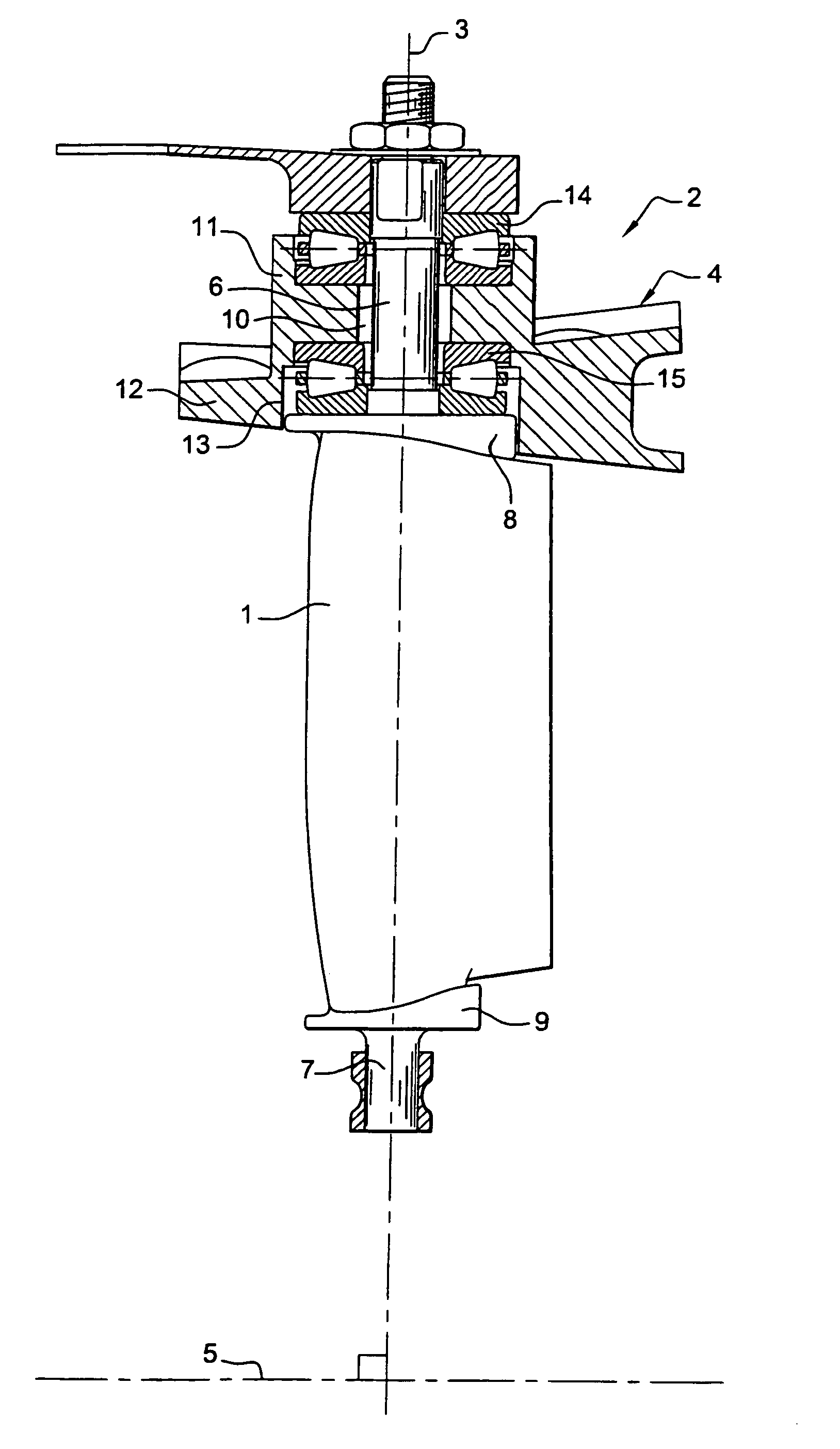
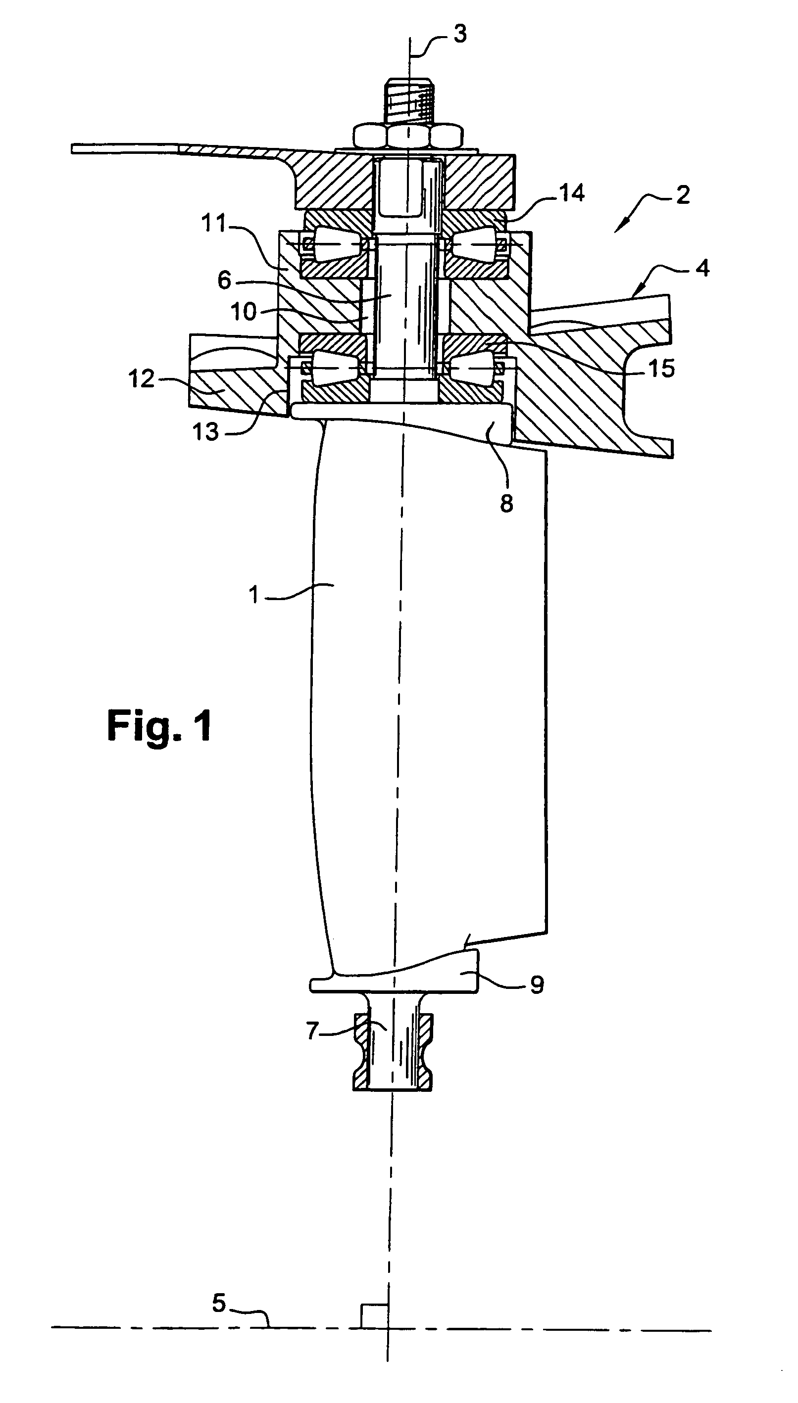
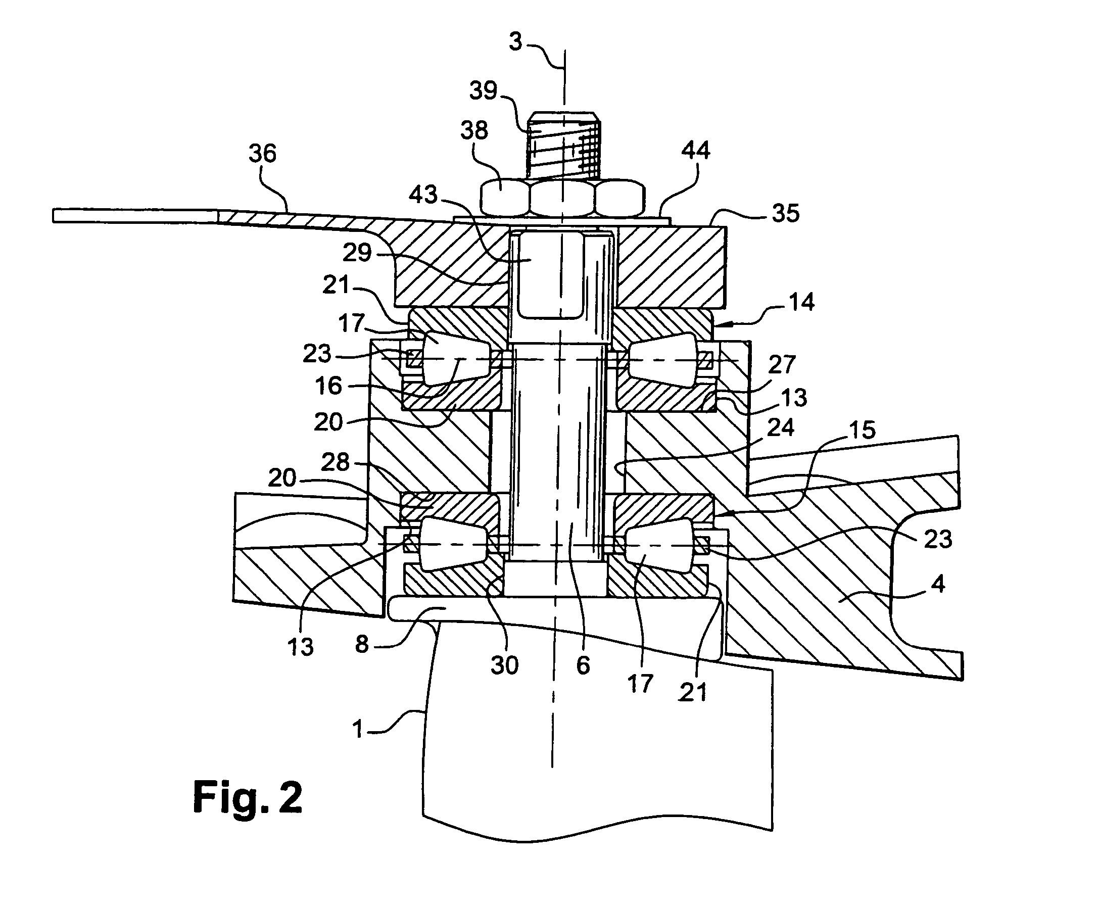
[0024]FIGS. 1 and 2 show a variable-pitch blade 1 in a compressor 2 of a turbomachine, the blade being capable of pivoting about its axis 3 relative to the stator 4 of the turbomachine. The axis 3 of the blade extends perpendicularly or otherwise relative to the axis of rotation 5 of the rotor (not shown) of the turbomachine. Two cylindrical pivots 6, 7 extend from the ends 8, 9 of the blade 1 along its pivot axis 3. The top pivot is formed by a cylindrical axial shank 6 of the blade 1 and is mounted in a cylindrical housing 10 formed in a thickening 11 of the stator 4, and the bottom pivot 7 extends from the other end 9 of the blade and is received in a cylindrical housing of a support (not shown) beside the rotor of the turbomachine. The axial shank 6 is guided in the cylindrical housing 10 of the stator 4 by a guide device of the invention. The guide device for the bottom pivot 7 is not shown in FIG. 1, such a device is not always needed to allow the blade 1 to pivot, and it may ...


PUM


Abstract

A guide device for guiding a variable-pitch blade, in particular in a turbomachine compressor, the blade having a pivot formed by a cylindrical axial shank mounted in a cylindrical housing of a casing and pivotally guided about an axis in said housing by bearings, where the bearings are abutment bearings with conical rollers, the axes of the rollers being substantially perpendicular to the pivot axis of the blade.

Description

CROSS REFERENCE TO RELATED APPLICATIONS[0001]This application is based upon and claims priority under 35 U.S.C. §119 from French Patent Application No. 0307707, filed Jun. 26, 2003.BACKGROUND OF THE INVENTION[0002]The present invention relates to a device for guiding a blade having a variable pitch angle, such as in particular a blade for directing air admitted into a turbomachine compressor, for example an aviation turbojet or turboprop.[0003]Known guide devices enable the stator blades of a turbomachine to turn about their own axes so as to rectify the flow of gas that has been deflected by the rotor blades. By controlling the extent to which the gas flow is rectified, which is done as a function of the differing speeds of the machine and of the dynamic characteristics of the gas, it is possible to increase performance of a turbomachine.[0004]In most designs, such as those described in documents FR-A-2 743 846, FR-A-2 814 206, and U.S. Pat. No. 5,215,434, such variable-pitch blade...

Claims


Application Information

Patent Timeline
Patent Type & Authority Patents(United States)
IPC IPC(8): F01D17/12F02C7/042F01D17/16F04D29/56F16C19/30F16C19/32F16C19/54F16C25/08F16C33/36
CPCF01D17/16F16C19/54F16C19/30F01D17/162F04D29/563
Inventor DEBENEIX, PIERREBROMANN, ALAINBUFFENOIR, FRANCOIS
Owner SN DETUDE & DE CONSTR DE MOTEURS DAVIATION S N E C M A
Why Eureka
Try Eureka