Land grid array socket having contact-protecting mechanism

a technology of contact protection mechanism and socket, which is applied in the direction of coupling device connection, electrical apparatus construction details, engagement/disengagement of coupling parts, etc., can solve the problems of inadvertent damage to contacts and impact on the reliability of electrical connections between

Active Publication Date: 2006-09-26
HON HAI PRECISION IND CO LTD
View PDF11 Cites 12 Cited by
  • Summary
  • Abstract
  • Description
  • Claims
  • Application Information

AI Technical Summary

Benefits of technology

[0010]Accordingly, a primary object of the present invention is to provide a land grid array (LGA) socket having contact-protecting mechanism for electrically connecting an LGA package with a printed circuit board (PCB), wherein the contact-protecting mechanism can prevent contacts received in the LGA socket from being damaged during installation of the LGA package.
[0012]In the first position, the LGA package is set on the floating frame, with the bottom surface thereof staying above and in substantially parallel with the contacting plane. When the LGA package is pressed down under a loading force, the floating frame together with the LGA package rest thereon, moves downwardly and vertically with respect to the contacting plane. In whole course of urging the LGA package, the bottom surface of the LGA package is in parallel with the contacting plane all along. As a result, the conductive pads arranged on the LGA package simultaneously register with corresponding contacts. Therefore, the contacts are free from being damaged by the LGA package, and reliable electrical interconnection between the LGA package and the PCB is ensured.

Problems solved by technology

This tends to cause inadvertent damage to the contacts 81 and impact reliability of the electrical connection between the LGA socket 8 and the PCB.
This problem arises particularly in high density and miniaturized LGA socket wherein the contacts are very closely spaced in a compact array.

Method used


Image

  • Land grid array socket having contact-protecting mechanism
  • Land grid array socket having contact-protecting mechanism
  • Land grid array socket having contact-protecting mechanism

Examples


Embodiment Construction

[0025]Reference will now be made to describe the preferred embodiment of the present invention in detail.

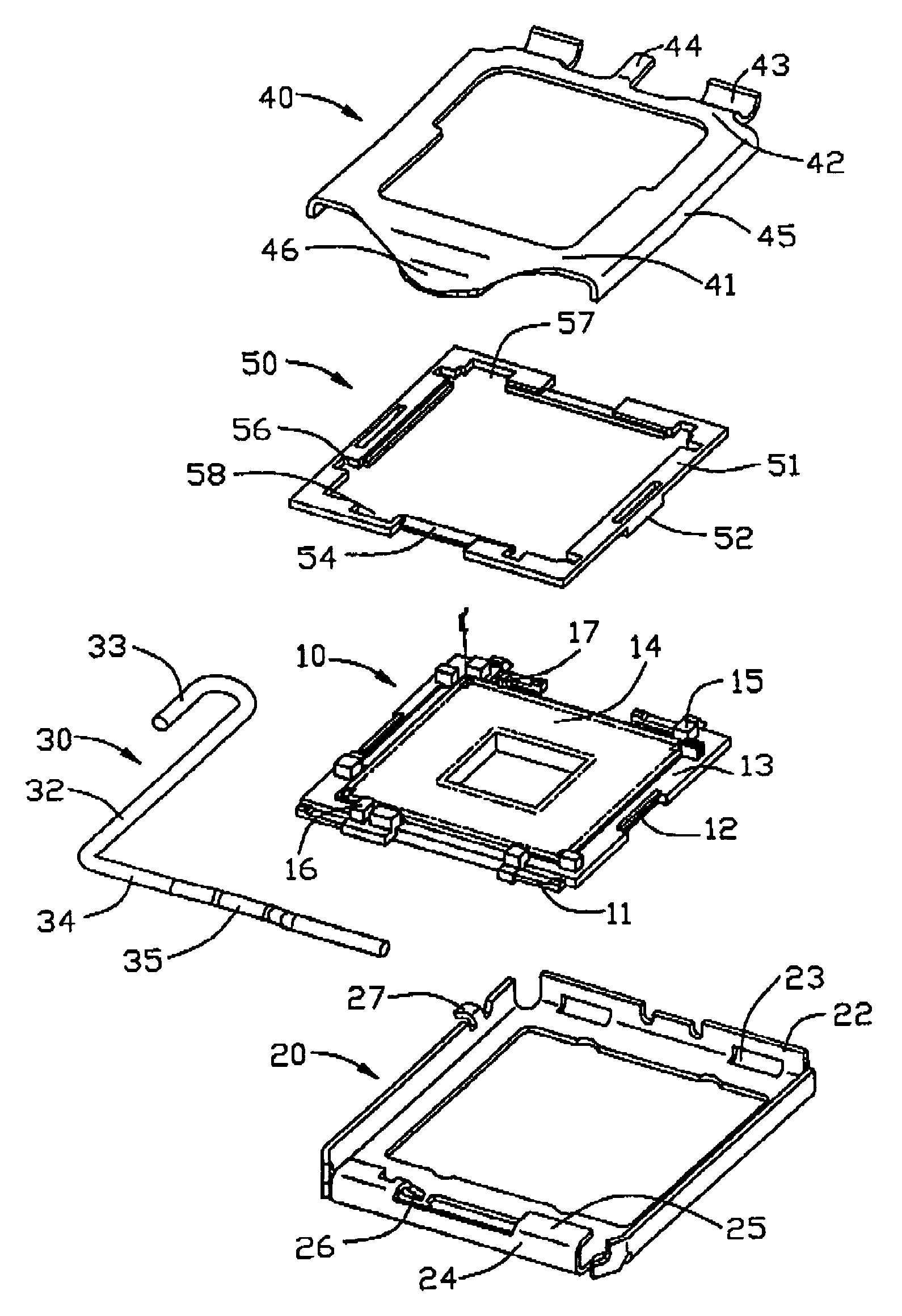
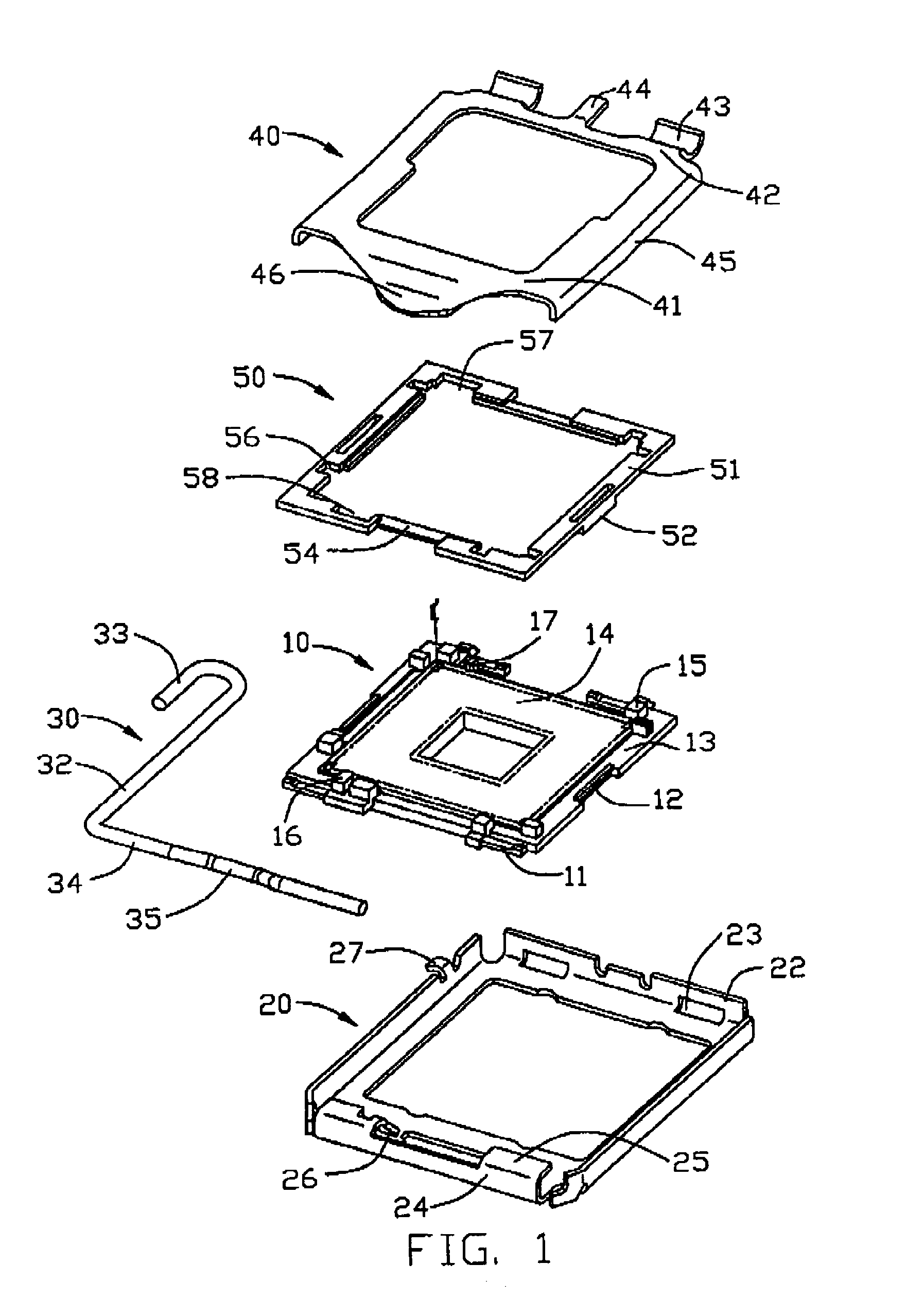
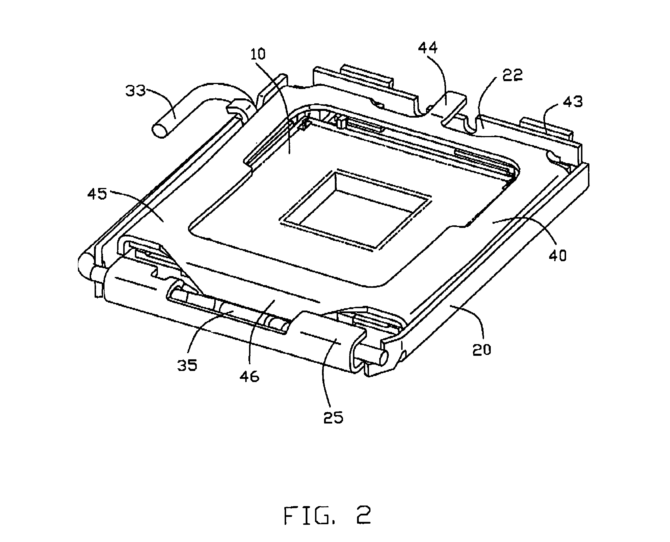
[0026]Referring to FIGS. 1 to 3, an LGA socket in accordance with a preferred embodiment of the present invention includes a socket body 10, a plurality of contacts (not shown) received in the socket body 10, a floating frame 50 floating on a plurality of flexible push fingers 11 formed on the socket body, a stiffener 20 arranged right round the socket body 10 and the floating frame 50, and a socket plate 40 and a load lever 30 pivotally attached to opposite ends of the stiffener 20, respectively.

[0027]Referring to FIGS. 4 and 5, the dielectric socket body 10 comprises an opening (not labeled) in a center thereof, a body section 13 at an outer side thereof, and an electrical region 14 recessed with respect to an upper surface of the body section 13 therebetween. The body section 13 has a front wall 132, a rear wall 134, and a pair of opposite lateral walls 131, 133 respectively a...


PUM


Abstract

An LGA socket includes a socket body (10), a number of contacts planted in the socket body, a hollowed floating frame (50) floating on a number of push fingers (11) formed on the socket body, a stiffener (20) disposed right round the socket body and the floating frame, and a socket plate (40) and a load lever (30) respectively mounted to opposite ends of the stiffener. The floating frame is provided with a number of receiving sections (54) to hold an LGA package (60). The floating frame with the LGA package held thereon is vertically movable between a free state in which the conductive pads of the LGA package do not engage with the contacts, and a compressed state in which the conductive pads of the LGA package resiliently register with corresponding contacts. Thus, damage to the contacts during installation is avoided and reliable electrical connection is ensured.

Description

BACKGROUND OF THE INVENTION[0001]1. Field of the Invention[0002]The present invention relates generally to electrical connectors, and more particularly to a land grid array (LGA) socket having contact-protecting mechanism for electrically connecting an LGA package with a circuit substrate, such as a printed circuit board (PCB).[0003]2. Description of the Prior Art[0004]An integrated circuit package having conductive pads arranged on a bottom surface thereof in an LGA fashion is known as an LGA package. LGA packages have been widely used due to relatively low height and reliable electrical characteristics.[0005]Connectors for removably connecting an LGA package with a PCB are known as LGA sockets. Normally, an LGA socket comprises a socket body, a plurality of contacts received in the socket body, a stiffener attached to the socket body, and a socket plate and a load lever pivotally attached to opposite ends of the stiffener respectively. The socket plate and the load lever can rotat...

Claims


Application Information

Patent Timeline
Patent Type & Authority Patents(United States)
IPC IPC(8): H01R12/00
CPCH01R12/88H01R13/6315H05K7/1061H05K7/1092
Inventor MA, HAO-YUN
Owner HON HAI PRECISION IND CO LTD
Why Eureka
Try Eureka