Joint compound sander

a joint compound and sander technology, which is applied in the field of portable electric sanders, can solve the problems of time-consuming at best, ineffective sanding paper, and tedious hand sanding with a screen,

Inactive Publication Date: 2006-09-26
WATSON ADAM DEWAIN
View PDF24 Cites 8 Cited by
  • Summary
  • Abstract
  • Description
  • Claims
  • Application Information

AI Technical Summary

Benefits of technology

[0015]An idler, driven by the spinning shaft of the motor, may spin in a plane parallel to the base. The idler may include an off axis drive lug engaged in the lateral slot thereby causing the base to oscillate with respect to the housing in the longitudinal direction.

Problems solved by technology

Traditional sanding paper typically become clogged with joint compound dust which renders the sanding paper ineffective quite quickly.
While this solution resolves the clogging problem, hand sanding with a screen remains tedious and the repetitive task of removing clogged joint compound from the screen is time consuming at best.
Existing hand held power sanders are also useful for sanding joint compound, however several problems exist with using existing power sanders.
First, if the power sander can only accommodate traditional sanding paper, the sanding paper will become clogged with joint compound dust very quickly rendering it ineffective.
Second, If the sander is of a an orbital or rotary type, it will tend to leave swirl marks and is impractical for sanding joint compound applied in a corner wherein two drywall panels meet at an acute angle.
Thirdly, even if the sander is limited to linear motion, it may still be impractical for sanding joint compound applied in a corner if the structure of the sander does not enable the abrasive to contact the joint compound in the corner.

Method used


Image

  • Joint compound sander
  • Joint compound sander
  • Joint compound sander

Examples


second embodiment

[0045]Referring briefly to FIG. 3b, a second exemplary pattern or mesas 78 and channels 80 is shown. Each mesa may be 1 / 16 inch wide and 1 / 16 inch in height formed a planar surface defining channels there-between. In this second embodiment, a perimeter mesa 75 extends around the periphery of the bottom surface 76 to restrict the flow of air into the channels 80 to only that air that has been drawn through the porous joint compound sanding screen 54.

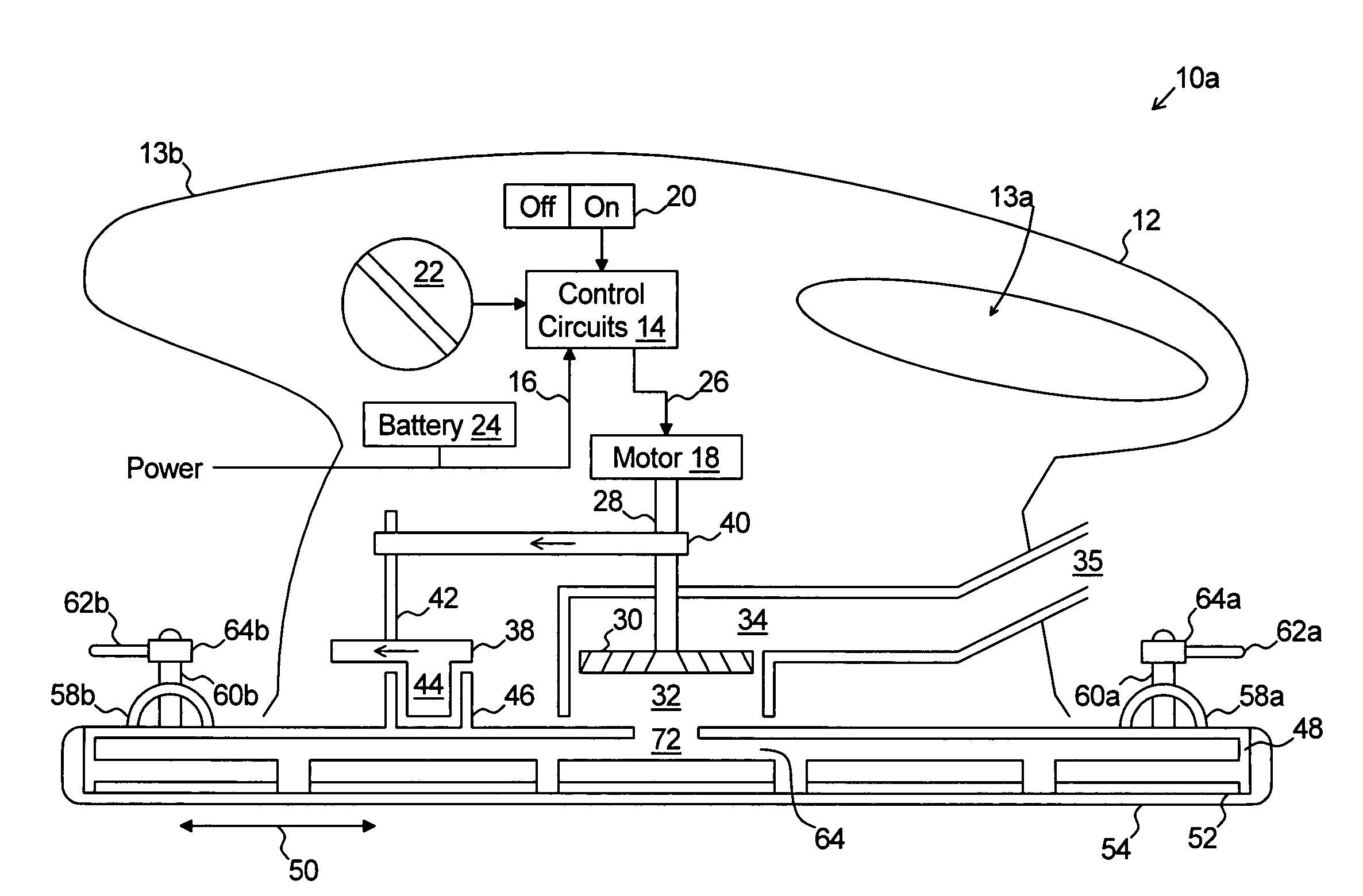
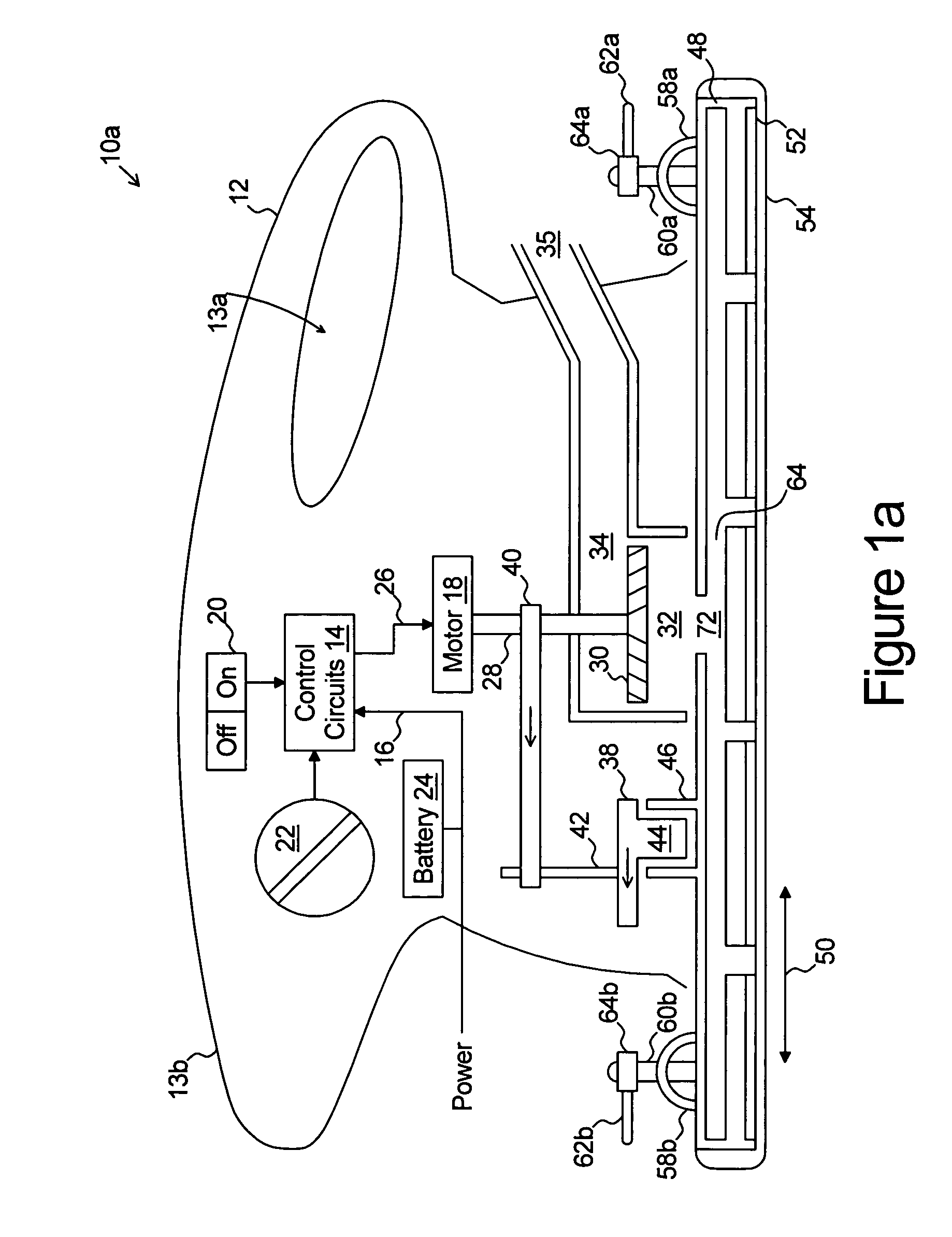
[0046]Returning to FIGS. 1a and 2, in operation, dust generated by the abrasive sanding screen 54 is drawn through the screen 54, along a channel 80 towards a dust collection aperture 74, through the dust collection aperture 74 into the vacuum manifold 64, through the central aperture 72 and inlet 32 of the fan 30, and then forced, by operation of the fan 30, into the exhaust manifold 34 and into the dust collection bag 36. By drawing the dust through the screen 54, clogging of the sanding screen 54 by dust becoming trapped in the screen ...

first embodiment

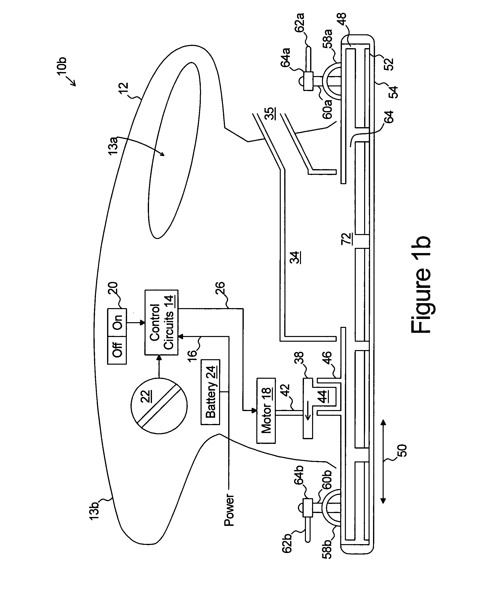
[0055]FIG. 1b shows a side view, partially cut away, of a second exemplary embodiment of a joint compound sander 10b in accordance with the present invention. The joint compound sander 10b, like the first embodiment joint compound sander 10a of FIG. 1a, comprises a housing 12 which functions as a chassis, forms the external surface of the sander 10b, and is shaped to include one or more handles 13a and 13b for easy operation by an operator.

[0056]Within the housing 12 is a control circuit 14. The control circuit 12 receives operating power 16 from a remote power source (such as through an electrical cable or from a battery 24). The control circuit 14 provides controlled power 26 to an electric motor 18 in accordance with input control signals provided by an on / off switched 20 and a variable speed control rheostat 22.

[0057]The motor 18 is secured to the housing 12 and includes a spinning shaft 28. The spinning shaft 28 is coupled to, and rotates, the idler 38. The idler 38 is secured ...


PUM


Abstract

A joint compound sanding device (10) comprises a hand held housing (12) and a bottom plate (66) coupled to the hand held housing (12). The bottom plate (66) includes a plurality of dust collection apertures (74) extending through the bottom plate (66) between a vacuum manifold (64) and a bottom surface (76). A plurality of dust collection channels (78) are formed in the bottom surface (76) defining mesas (80) there between. The mesas support a porous joint compound sanding screen (54). A motor is coupled to hand held housing (12) and includes a rotating shaft coupled and rotating to a dust collection fan (30) such that air is drawn through a porous joint compound sanding screen (54), through the channels (78), through the dust collection apertures (74) into the vacuum manifold (64) and through the fan inlet (32) and expelling the air into an exhaust manifold (34).

Description

TECHNICAL FIELD[0001]The present invention relates to portable electric hand tools, and in particular to a portable electric sander useful for capturing dust generating when sanding joint compound and useful for sanding joint compound in acute angle corners.BACKGROUND OF THE INVENTION[0002]When installing drywall in a facility, large panels of drywall are nailed or screwed to structural studs. Each nail or screw leaves a recess in the surface of the dry wall panel and gaps exist between adjacent dry wall panels. Typically the gaps between panels are covered with a tape and a joint compound is used to: i) fill the recesses in the surface caused by the nail or screw; ii) cover and blend the surface of the tape to the surface of the panels; and iii) fill remaining damage and imperfections in the surface of the panels.[0003]The joint compound is applied in a wet state. After the joint compound hardens and dries, it is sanded such that a smooth surface is formed across multiple dry wall ...

Claims


Application Information

Patent Timeline
Patent Type & Authority Patents(United States)
IPC IPC(8): B24B23/00B24B23/04B24B55/10
CPCB24B55/105B24B23/04
Inventor WATSON, ADAM DEWAIN
Owner WATSON ADAM DEWAIN
Why Eureka
Try Eureka