Data transmission cable

a data transmission and cable technology, applied in the direction of flat/ribbon cables, insulated conductors, cables, etc., can solve the problems of the inability to wire and construct cables on the surface of walls, ceilings, floors, etc., and achieve the effect of deteriorating the quality of the signal, and improving the handiness of the cabl

Inactive Publication Date: 2006-09-26
SONY CORP
View PDF20 Cites 16 Cited by
  • Summary
  • Abstract
  • Description
  • Claims
  • Application Information

AI Technical Summary

Benefits of technology

[0008]In light of the above-described situation, it is an object of the present invention to provide a cable for data transmission which can be wired and constructed without damaging a surface of a wall, ceiling, floor or the like, without using any clamps and which does not degrade appearance of a wired space. In addition, it is another object of the present invention to provide a cable for data transmission in which the cable provided with a plurality of core wires can be wired and constructed in a state of less crosstalk.SUMMARY OF THE INVENTION
[0019]A cable for data transmission according to a second aspect of the present invention comprises a plurality of core wires provided at predetermined intervals, respectively and each having a medium that transmits data, and a coating member having stickiness which covers the aforementioned plurality of core wires. In the present invention, in a case where a so-called multi-conductor cable is wired and constructed, the cable can be easily stuck to a wall, ceiling, floor or the like and crosstalk between the respective core wires inside the cable can be reduced as much as possible. Concretely, by arranging wire medium core wires at a necessary distance from each other at predetermined intervals inside the coating member, the multi-conductors can be easily realized. Furthermore, by making the coating members multiple-stage, a larger number of core wires can be arranged.

Problems solved by technology

However, since the fixation of the cable with such fittings or the like requires a number of fittings, it is difficult to conceal all the fittings and the cable sags between the fittings owing to its own weight, which degrades the appearance.
Furthermore, in a rented house, the use of a screw or a nail is often prohibited and thus, as a matter of fact, the cable cannot be wired and constructed on a surface of a wall, ceiling, floor or the like.
However, in such a technique, since the both-sided sticky tape is stuck to the wall or the like and the cable is further stuck on the both-sided sticky tape, the working is duplicated.
In this case, for example, when a location where the tape is stuck is wrong, the tape is detached and the working needs to be carried out again, which is troublesome.
The cable of this structure also has a problem that since the core wires are normally included in the coating layer in contact with each other, crosstalk between the core wires is significant, thereby leading to deterioration of a signal in quality.

Method used


Image

  • Data transmission cable
  • Data transmission cable
  • Data transmission cable

Examples


first embodiment

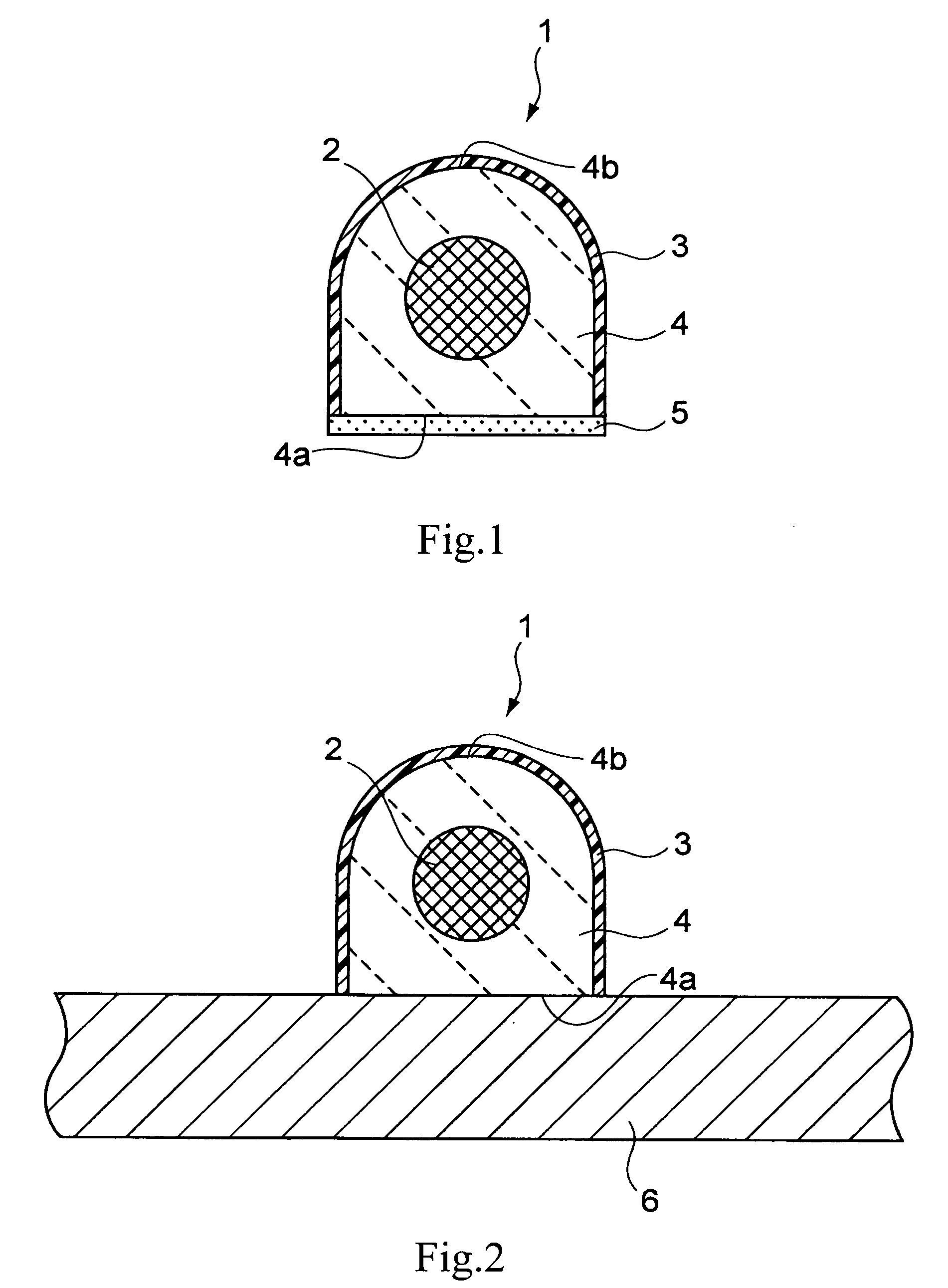
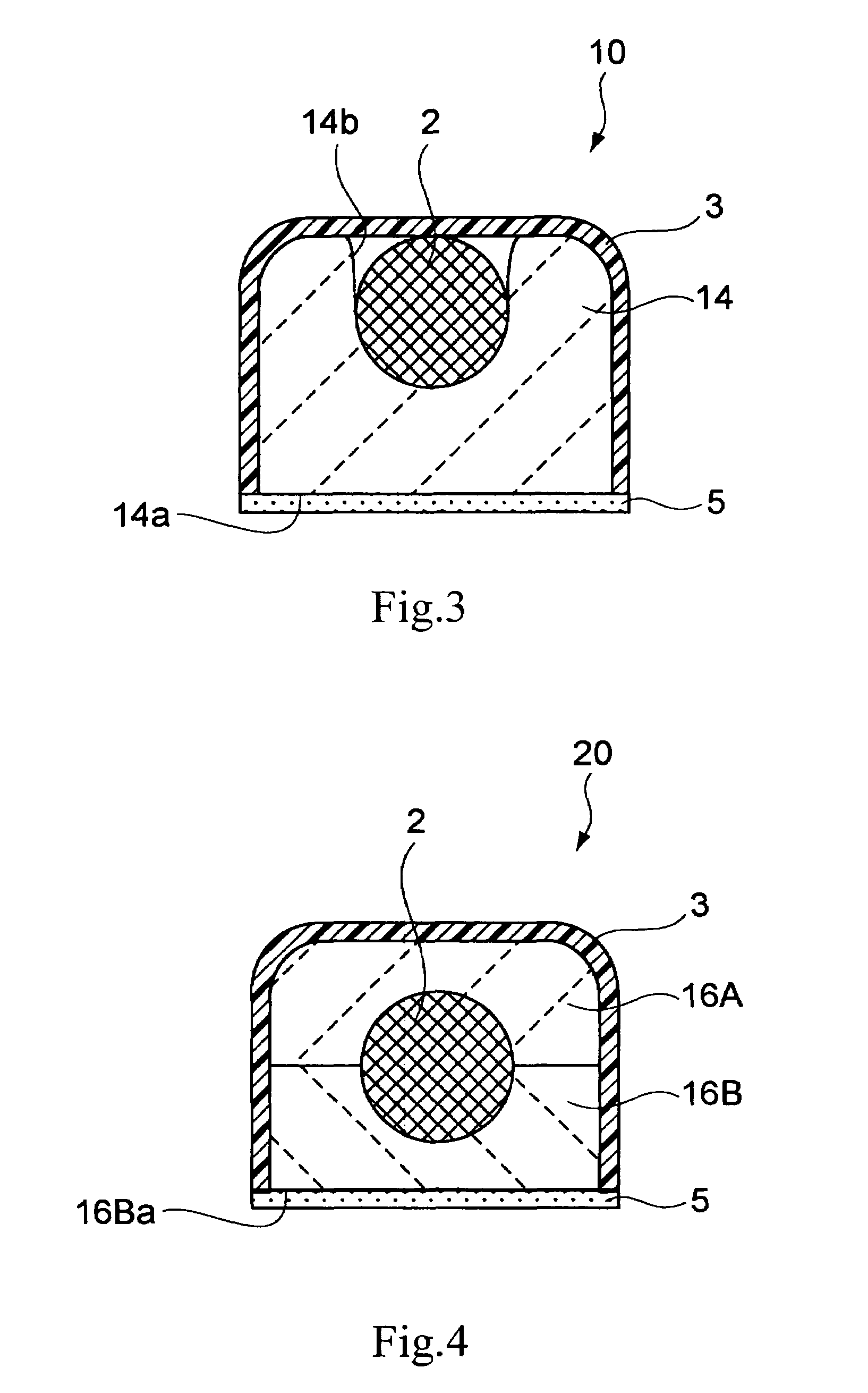
[0035]FIG. 1 is a cross-sectional view showing a cable for data transmission according to the present invention. This cable 1 is an optical fiber cable or a general electric cable, for example. In this cable 1, a core wire 2 is covered with a coating member 4 having stickiness and this coating member 4 is covered with a cover film 3 and a release paper 5. This coating member 4 has a flat surface portion 4a formed by making part of a surface of the coating member 4 into a flat surface and a curvature portion 4b including a portion formed into a curvature shape at a position opposed to the flat surface portion 4a.

[0036]The release paper 5 is stuck by stickiness of the coating member 4 to the flat surface portion 4a formed by making portion of the surface of the coating member 4 into a flat surface, and the cover film 3 is stuck to the curvature portion 4b. The cover film 3 may be stuck to the coating member 4 only by the stickiness of the coating member 4, or may be stuck by an adhes...

third embodiment

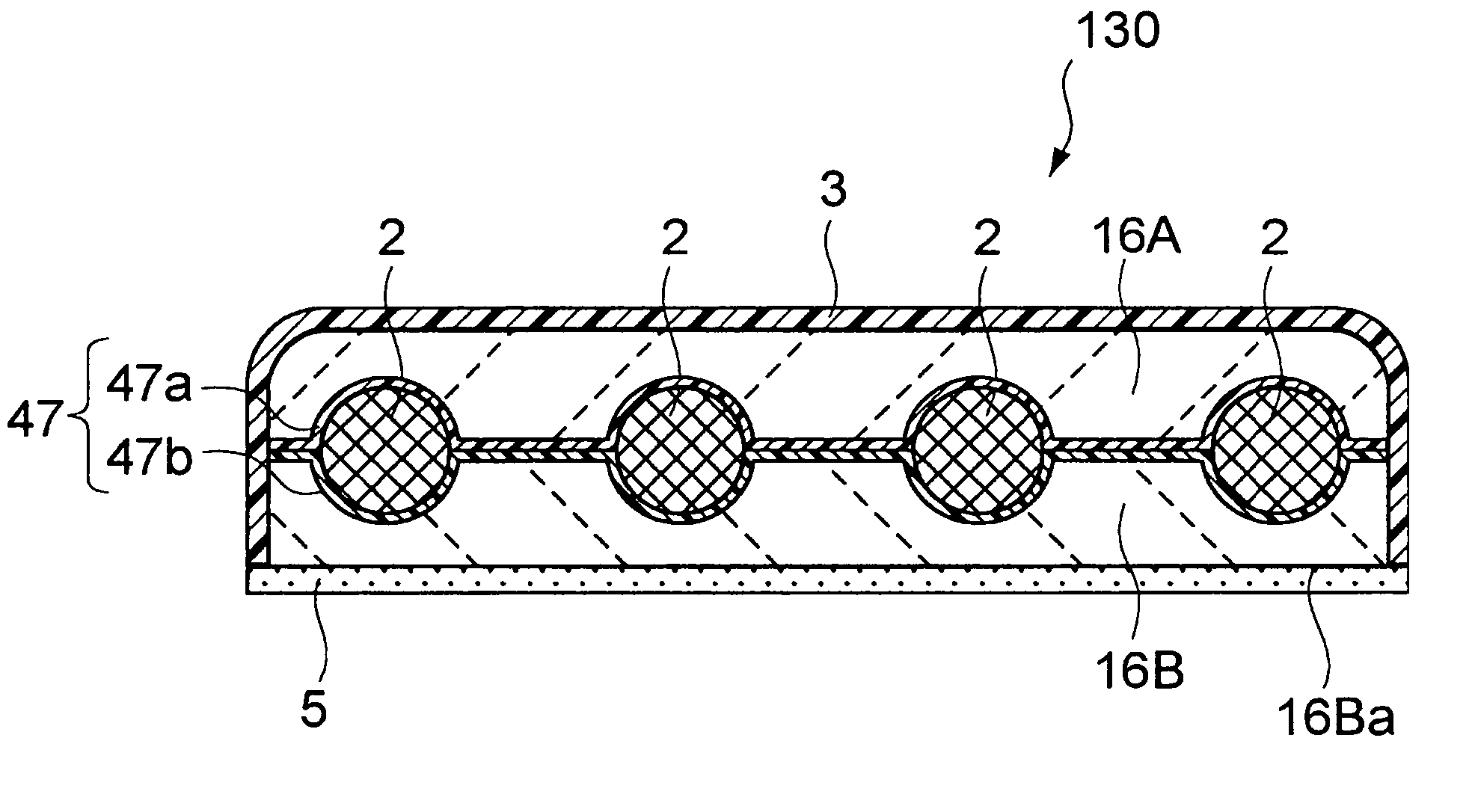
[0046]FIG. 4 is a cross-sectional view of a cable for data transmission according to the present invention. In this cable 20, a coating member having stickiness is provided in such a manner that it is divided into two layers of an upper coating member 16A and a lower coating member 16B in the figure to sandwich the core wire 2. The release paper 5 is stuck to a flat surface portion 16Ba of the lower coating member 16B.

fourth embodiment

[0047]FIG. 5 is a cross-sectional view of a cable for data transmission according to the present invention, and this cable 30 is a so-called multi-conductor cable. In this embodiment, for example, four core wires 2 are sandwiched and fixed between the upper coating member 16A and lower coating member 16B both having stickiness. In the present embodiment, since the core wires are arranged apart from each other at predetermined intervals, crosstalk can be reduced, and thus deterioration of a signal in quality can be prevented.


PUM

PropertyMeasurementUnit
lengthaaaaaaaaaa
areaaaaaaaaaaa
shapeaaaaaaaaaa

Abstract

There is provided a cable for data transmission which can be wired and constructed without damaging a surface of a wall, ceiling, floor or the like, without using any clamps and which does not degrade appearance of a wired space, and further, allows the wiring construction of the cable provided with a plurality of core wires in a state of less crosstalk. A cable (1) for data transmission includes a core wire (2) having a medium that transmits data and a coating member (4) having adhesiveness and coating at least part of the core wire (2). In this way, because of the adhesiveness of the coating member (4), it is easy to stick the cable onto a wall (6) or the like. Moreover, since a wiring construction of the cable on a surface of the wall (6) or the like without using a clamp, screw or nail is made possible, only the cable is exposed on the surface of the wall (6) or the like and the appearance thereof is improved.

Description

[0001]The present invention relates to a cable for data transmission, such as an optical fiber cable and an electric cable.[0002]In the past, in a case where a wire medium such as an optical fiber cable and an electric cable is wired and constructed in a wall, ceiling, floor or the like of a housing, for example, clamps have been arranged at constant intervals along a longitudinal direction of the cable to fix the cable.[0003]However, since the fixation of the cable with such fittings or the like requires a number of fittings, it is difficult to conceal all the fittings and the cable sags between the fittings owing to its own weight, which degrades the appearance.[0004]Furthermore, in a rented house, the use of a screw or a nail is often prohibited and thus, as a matter of fact, the cable cannot be wired and constructed on a surface of a wall, ceiling, floor or the like.[0005]In order to solve such a problem, for example, in a case where a cable is extended along a wall of a housing...

Claims


Application Information

Patent Timeline
Patent Type & Authority Patents(United States)
IPC IPC(8): H01B7/08G02B6/44H01B7/00H01B11/00H01B11/06H02G3/30
CPCH02G3/305H02G3/26G02B6/4471H01B7/08H01B7/40H01B7/1875H01B11/22
Inventor TSUKAHARA, NOBUHIKOTORIUMI, YOICHISHINTANI, KENJIHASHIMOTO, HIROFUMI
Owner SONY CORP
Why Eureka
Try Eureka