Light emitting device and method for making same

a light-emitting device and micro-cavity technology, applied in the direction of lasers, semiconductor laser excitation apparatus, excitation process/apparatus, etc., can solve the problems of reducing the optical efficiency of the micro-cavity, limiting the choice of materials that can be used, and long time-consuming production of said mirrors

Inactive Publication Date: 2006-09-26
COMMISSARIAT A LENERGIE ATOMIQUE ET AUX ENERGIES ALTERNATIVES
View PDF5 Cites 63 Cited by
  • Summary
  • Abstract
  • Description
  • Claims
  • Application Information

AI Technical Summary

Problems solved by technology

However, a stop layer in HgTe is very absorbent and significantly reduces the optical efficiency of the micro-cavity.
The production of said mirror takes a long time, due to the low rate of crystalline growth.
Moreover, the epitaxy requires the crystalline parameter of the different layers of the mirror to be attuned, which limits the choice of materials that can be used.

Method used


Image

  • Light emitting device and method for making same
  • Light emitting device and method for making same
  • Light emitting device and method for making same

Examples


Embodiment Construction

[0026]The aim of the present invention is to overcome the disadvantages of said known techniques.

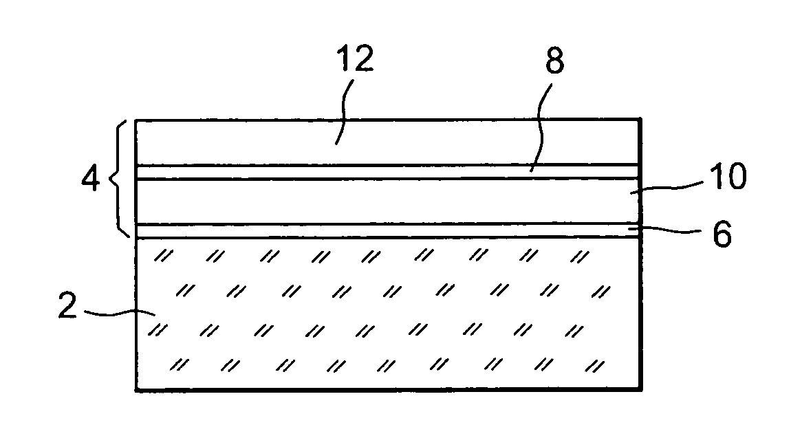
[0027]More precisely, the aim of the invention is a light emitting device comprising a stack that comprises:[0028]a substrate,[0029]an etching stop layer on said substrate,[0030]a first barrier layer on said stop layer,[0031]a light emitting layer on said first barrier layer, and[0032]a second barrier layer on said emitting layer, said device being characterised in that the etching stop layer and the emitting layer are in CdxHg1−xTe.

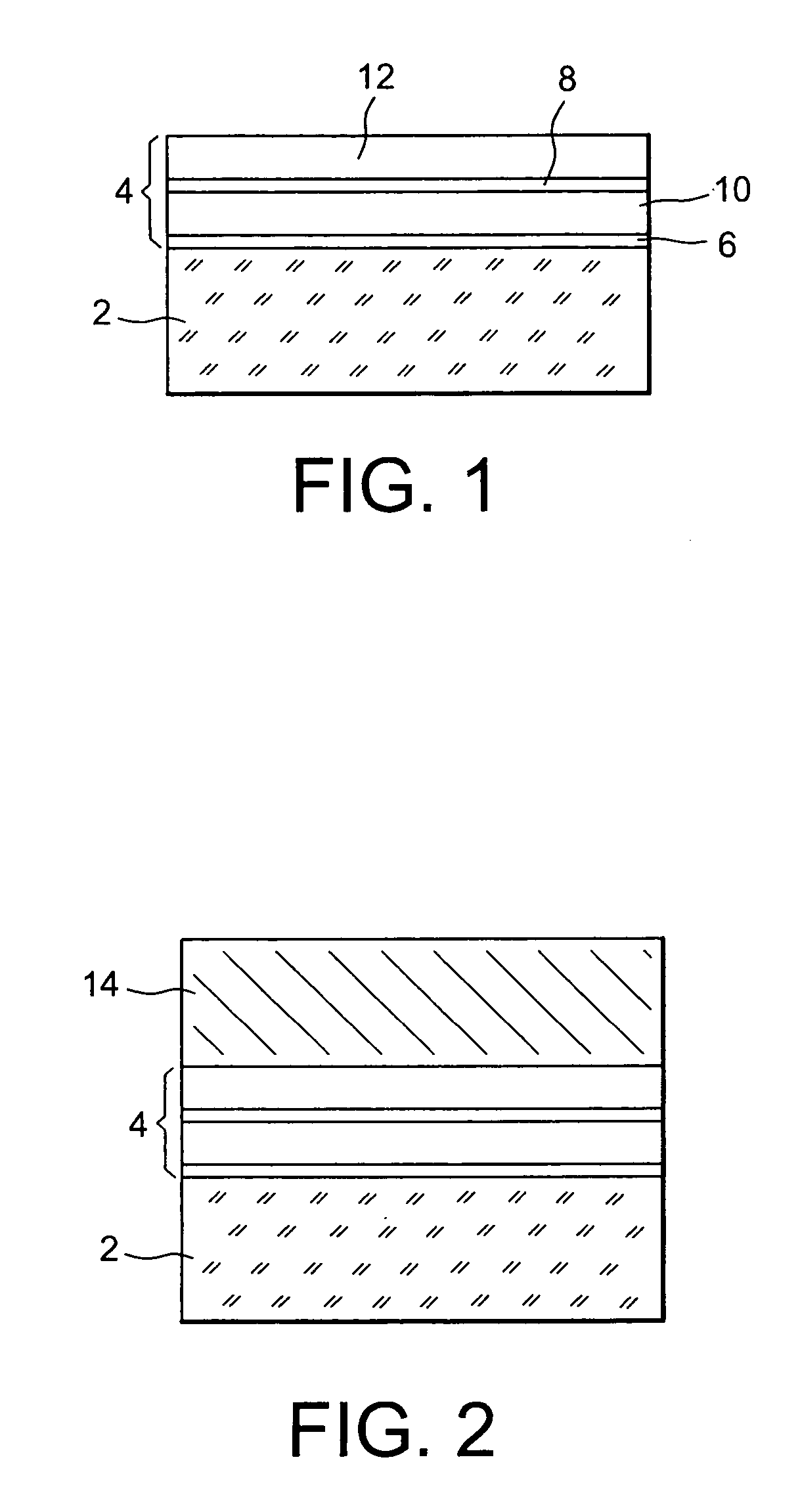
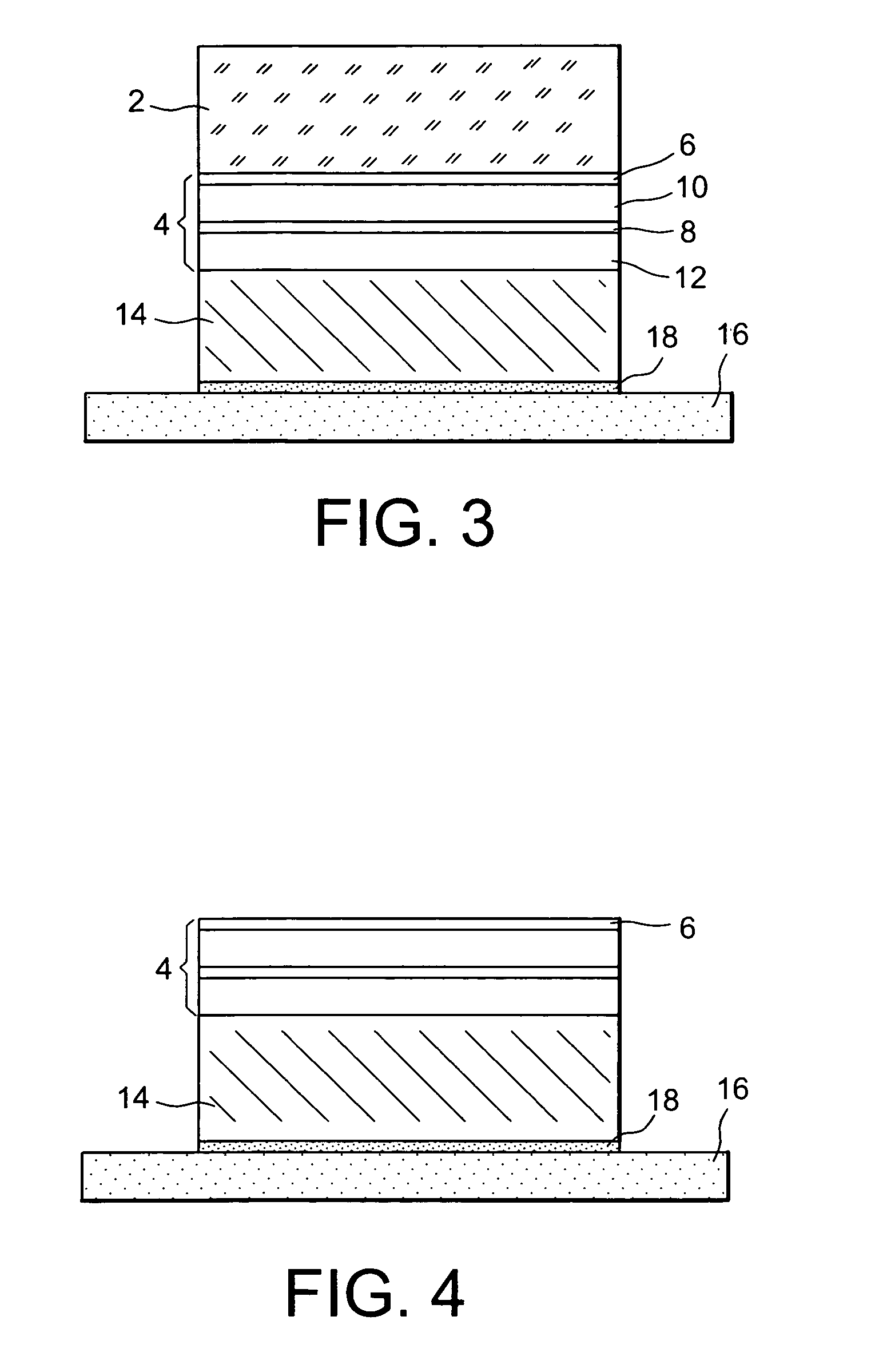
[0033]A further aim of the invention is a method for producing a light emitting device, said device comprising an active part and a micro-cavity, delimited by first and second mirrors and containing the active part, said active part being formed on a substrate and comprising an etching stop layer at the interface of said active part with the substrate, and an emitting layer suited to emitting light when it is optically pumped through the first mirror, method ...


PUM


Abstract

A light emission device and method for producing the device. The device includes, on a substrate, a stack including an etching stop layer, a first barrier layer, an emitting layer, and a second barrier layer. The stop layer is of the same nature as the emitting layer. One may form a mirror on the stack, eliminate the substrate by etching, and form another mirror on the stop layer to obtain a micro-cavity. The device may be applied in particular to the detection of gas.

Description

TECHNICAL FIELD[0001]The present invention concerns a micro-cavity light emitting device and a method for producing said device.[0002]More specifically, the invention concerns a micro-cavity light emitting device that emits light in the mid infrared, which extends from 2 μm to 6 μm, and a method for producing said device.[0003]The invention applies, in particular:[0004]to the detection of gases such as polluting gases or greenhouse effect gases, more specifically in the field of the automobile industry (measuring the concentration of exhaust gases) and in the field of climatology (measuring the carbon dioxide in the atmosphere), and[0005]to the automatic sorting of plastics that also absorb in the infrared at different wavelengths according to their composition.STATE OF THE PRIOR ART[0006]A micro-cavity light emitting device is a planar type of device, comprising an emitting structure that one photo-pumps by means of a laser diode.[0007]Said emitting structure comprises an active pa...

Claims


Application Information

Patent Timeline
Patent Type & Authority Patents(United States)
IPC IPC(8): H01L31/0328H01L31/00H01L33/00H01L33/10H01L33/28H01S5/04H01S5/327
CPCH01S5/327H01L33/0079H01L33/105H01S5/041H01L33/28H01L33/0093
Inventor PICARD, EMMANUELHADJI, EMMANUELZANATTA, JEAN-PAUL
Owner COMMISSARIAT A LENERGIE ATOMIQUE ET AUX ENERGIES ALTERNATIVES
Why Eureka
Try Eureka