Radiation system, lithographic apparatus, device manufacturing method and device manufactured thereby

a technology of lithographic apparatus and radiation system, which is applied in the direction of electrical apparatus, printers, instruments, etc., can solve the problems of radiation loss (i.e. energy) in the direction of the rest of the illumination system, radiation beam entering the illumination system in an erroneous way, and partly reflecting mirrors are not suitable for very short wavelengths, so as to achieve the effect of minimal energy loss

Active Publication Date: 2006-09-26
ASML NETHERLANDS BV
View PDF6 Cites 8 Cited by
  • Summary
  • Abstract
  • Description
  • Claims
  • Application Information

AI Technical Summary

Benefits of technology

[0007]It is an aspect of the present invention to provide a radiation system including a radiation generator and an illumination system wherein a relative position of the radiation generator with respect to the illumination system can be measured with a minimal loss of energy.

Problems solved by technology

When the radiation generator is not correctly positioned, the radiation beam will enter the illumination system in an erroneous way.
However, to align a radiation generator relative to an illumination system, such a zero sensor has either a measurement range or a measurement accuracy that does not meet the requirements.
Using a partly reflective mirror will result in a loss of radiation (i.e. energy) in the direction of the rest of the illumination system.
Furthermore, such a partly reflecting mirror is not suitable for very short wavelengths in combination with the high radiation intensity used in EUV lithography systems.

Method used


Image

  • Radiation system, lithographic apparatus, device manufacturing method and device manufactured thereby
  • Radiation system, lithographic apparatus, device manufacturing method and device manufactured thereby
  • Radiation system, lithographic apparatus, device manufacturing method and device manufactured thereby

Examples


Embodiment Construction

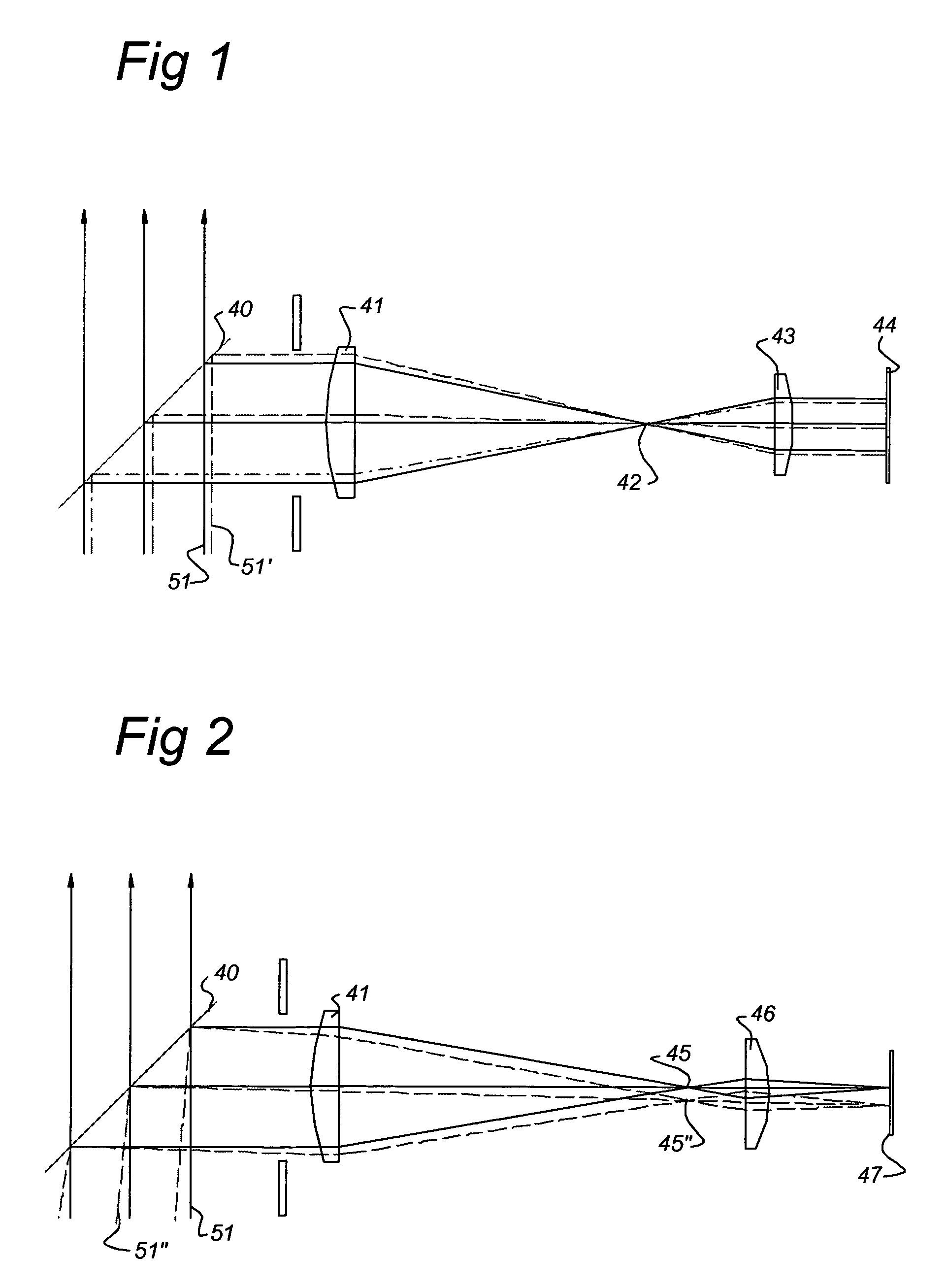
[0038]Referring to FIG. 1, a beam measuring system according to the prior art is fixed to an illumination system (not shown) and includes a partly transparent / partly reflective mirror 40 which is positioned in a beam of radiation 51 coming from a radiation generator (not shown). Three arrows in FIG. 1 indicate the radiation passing the mirror 40. Part of the radiation beam 51 is reflected to a lens 41. The lens 41 is configured to form an intermediate focus 42. A lens 43 is configured to receive radiation coming from the intermediate focus 42. The lens 43 is configured to form a demagnified image of beam 51 on a position sensor 44. The position sensor 44 is configured to detect the position of the beam 51 on the position sensor 44. When the radiation generator is incorrectly positioned with respect to the illuminator (i.e. measuring system) a radiation beam 51′ will hit the mirror 40. Radiation from the beam 51′ is indicated by dashed lines. The radiation from beam 51′ will pass len...


PUM

PropertyMeasurementUnit
wavelengthaaaaaaaaaa

Abstract

A radiation system includes a radiation generator to generate radiation, a source, and an illumination system configured to receive the radiation and provide a beam of radiation. The illumination system includes a beam measuring system configured measure at least one of position and tilt of the beam of radiation relative to the illumination system and a projecting device configured to redirect only a part of a cross section of the beam of radiation to the beam measuring system. The beam measuring system may include several position sensors, the readouts of which can be used to determine incorrect alignment of the radiation source with respect to the illumination system. Diaphragms are connected to the collector of the radiation generator, so that in addition to X, Y, and Z corrections, Rx, Ry and Rz corrections are possible.

Description

BACKGROUND OF THE INVENTION[0001]1. Field of the Invention[0002]The present invention relates to a radiation system, a lithographic apparatus including a radiation system, and a device manufacturing method.[0003]2. Description of the Related Art[0004]A lithographic apparatus is a machine that applies a desired pattern onto a target portion of a substrate. Lithographic apparatus can be used, for example, in the manufacture of integrated circuits (ICs). In that circumstance, a patterning device, such as a mask, may be used to generate a circuit pattern corresponding to an individual layer of the IC, and this pattern can be imaged onto a target portion (e.g. including part of one or several dies) on a substrate (e.g. a silicon wafer) that has a layer of radiation-sensitive material (resist). In general, a single substrate will contain a network of adjacent target portions that are successively exposed. Known lithographic apparatus include steppers, in which each target portion is irrad...

Claims


Application Information

Patent Timeline
Patent Type & Authority Patents(United States)
IPC IPC(8): G03B27/74G01B11/00G03B27/42G03B27/68G01B11/26G02B5/08G03F7/20H01L21/027
CPCG03F7/70141G03F7/70641G03F7/70858
Inventor DIERICHS, MARCEL MATHIJS THEODORE MARIEEURLINGS, MARKUS FRANCISCUS ANTONIUSFRIJNS, OLAV WALDEMAR VLADIMIR
Owner ASML NETHERLANDS BV
Why Eureka
Try Eureka