Double-nosed inductive transducer with reduced off-track writing

a transducer and inductive technology, applied in the field of electromagnetically polarized transducers, can solve the problems of difficult formation of magnetic anisotropy of the other magnetic pole, difficult transmission of high-intensity magnetic flux through the pole tip portion, and inability to transmit high-intensity magnetic flux, etc., to achieve the effect of limiting off-track writing, increasing magnetic flux, and increasing the amount of high-magnet moment materials

Inactive Publication Date: 2006-09-26
WESTERN DIGITAL TECH INC
View PDF16 Cites 156 Cited by
  • Summary
  • Abstract
  • Description
  • Claims
  • Application Information

AI Technical Summary

Benefits of technology

[0007]A geometry of a pole layer is disclosed that increases the amount of high magnetic moment material near the pole tip surface while limiting off-track writing produced by such material. Such geometry may increase a magnetic flux to be transmitted through the pole tip surface while avoiding leakage of such magnetic flux onto the recording media from areas of the pole layer other than the pole tip surface. For example, an inductive transducer is disclosed that has a double-nosed ferromagnetic trailing pole layer disposed adjacent to electrically conductive coil sections, which are also disposed adjacent to a leading pole layer. The trailing pole layer has a trailing pole tip disposed adjacent to a media-facing surface, a trailing pole yoke disposed distal to the media-facing surface, and a trailing pole nose disposed between the trailing pole tip and the trailing pole yoke. This summary merely lists a few aspects of the disclosure while the invention is defined by the claims appended below.

Problems solved by technology

As track width is decreased, however, it becomes more difficult to transmit high-intensity magnetic flux through the pole tip portion.
Ishiwata et al. teach that when the width of the pole-like distal end portion of the other magnetic pole decreases, the magnetic anisotropy of the other magnetic pole becomes difficult to form, and tends to be formed in an undesirable direction.
The “recessed portions” that remain adjacent the pole tip would disrupt the air-bearing surface, however, as well being difficult to form.

Method used


Image

  • Double-nosed inductive transducer with reduced off-track writing
  • Double-nosed inductive transducer with reduced off-track writing
  • Double-nosed inductive transducer with reduced off-track writing

Examples


Embodiment Construction

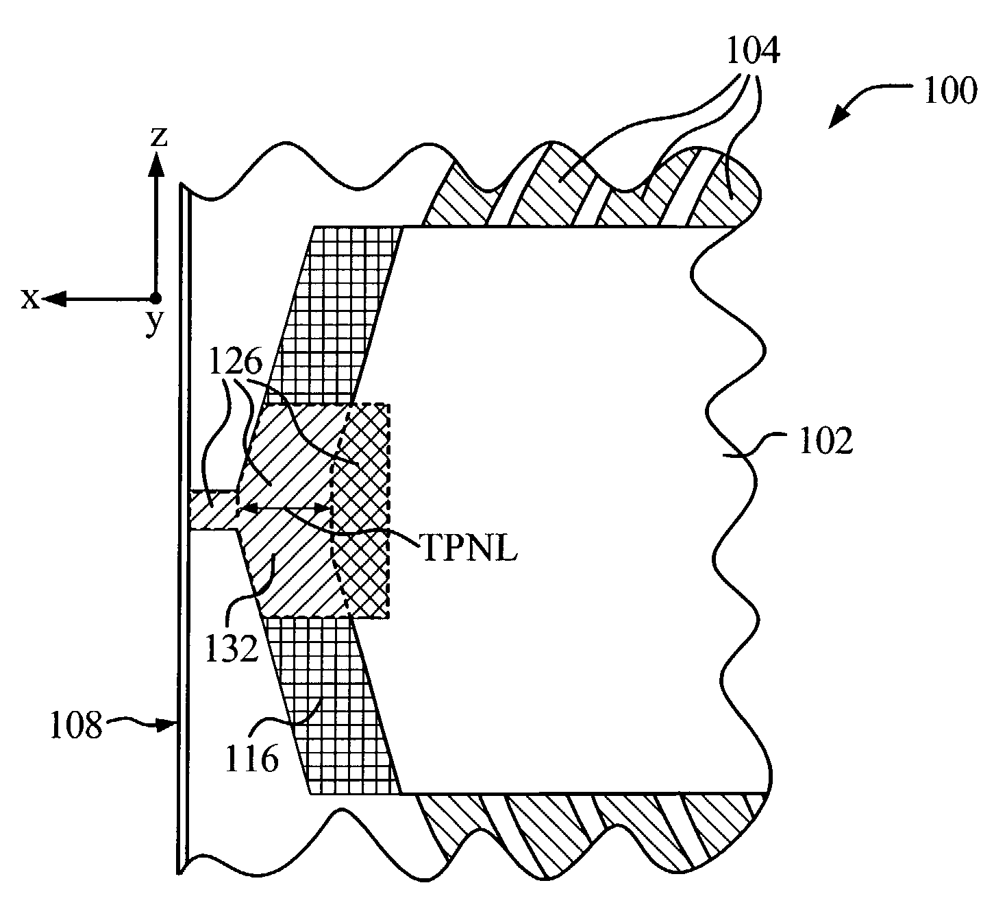
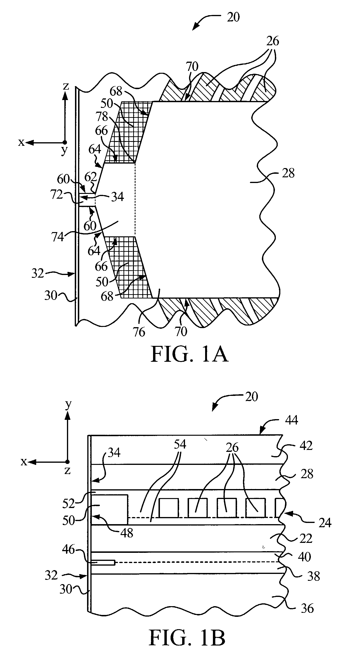
[0024]FIG. 1B depicts a first embodiment in accordance with the present invention and shows a cutaway cross-sectional view of a merged inductive and magnetoresistive (MR) transducer 20 of a read / write head. Transducer 20 has been formed in a plurality of adjoining solid layers on a wafer substrate, not shown. A first magnetically soft shield layer 36 has been formed adjacent to the wafer substrate. A first layer of nonmagnetic, electrically insulating material 38 is disposed on the shield layer 36, adjoining an MR sensor 46. The MR sensor 46 can be any sensor that utilizes a change in resistance associated with a change in magnetic field to sense that field, which may be measured as a change in current or voltage across the sensor, as the sensor passes over a track on a medium upon which information is stored.

[0025]A second layer of nonmagnetic, electrically insulating material 40 is disposed between the MR sensor 46 and a second magnetically soft shield layer. The shield layer also...


PUM

PropertyMeasurementUnit
widthaaaaaaaaaa
tip lengthaaaaaaaaaa
nose widthaaaaaaaaaa

Abstract

A thin film electromagnetic head has an inductive transducer with a double-nosed ferromagnetic trailing pole layer. The trailing pole layer has a trailing pole tip disposed adjacent to a media-facing surface, a trailing pole yoke disposed distal to the media-facing surface, and a trailing pole nose disposed between the trailing pole tip and the trailing pole yoke. The media-facing surface extends as a substantially flat surface in all directions from the trailing pole tip. The length of the trailing pole nose may be at least twice as long as the trailing pole tip length. The width of the trailing pole nose can be 10 to 30 times as wide as the trailing pole tip width. An inductive transducer having a double-nosed trailing pole layer provides a higher ratio of on-track to off-track write fields, thereby improving the density with which data can be written to the recording media. Such a double-nosed trailing pole layer can be used in transducers for either longitudinal or perpendicular magnetic recording.

Description

BACKGROUND OF THE INVENTION[0001]The present invention relates to electromagnetic transducers, which may for example be employed in thin film inductive write heads of the type formed on the trailing ends of air bearing sliders used in magnetic recording disk drives.[0002]An inductive transducer used for writing and / or reading magnetic information on storage media, such as a disk or tape, typically includes electrically conductive coil windings that encircle a magnetic core. The magnetic core has leading and trailing pole layers. The pole layers have pole tip portions adjacent to the recording media. The magnetic core is interrupted by a submicron nonmagnetic gap disposed between the pole tip portions to divert magnetic flux to the media during writing. To write to the media, electric current is flowed through the coil windings, which produces magnetic flux in the core encircling the coil windings, the magnetic flux fringing across the nonmagnetic gap adjacent to the media so as to w...

Claims


Application Information

Patent Timeline
Patent Type & Authority Patents(United States)
IPC IPC(8): G11B5/187
CPCG11B5/3116
Inventor WANG, YUGANGSTOEV, KROUMLIU, FRANCISCHEN, YINGJIAN
Owner WESTERN DIGITAL TECH INC
Why Eureka
Try Eureka