Carbonation system and method

a carbonation system and liquid technology, applied in the field of carbonation systems and methods, can solve the problems of long time requirements and relatively high pressure requirements

Inactive Publication Date: 2006-10-03
PRIMO WATER HLDG INC
View PDF15 Cites 50 Cited by
  • Summary
  • Abstract
  • Description
  • Claims
  • Application Information

AI Technical Summary

Problems solved by technology

The main problem with this method is that it is only effective if relatively high pressures are used in the carbonation chamber.
The problem with this method is t

Method used


Image

  • Carbonation system and method
  • Carbonation system and method
  • Carbonation system and method

Examples


Embodiment Construction

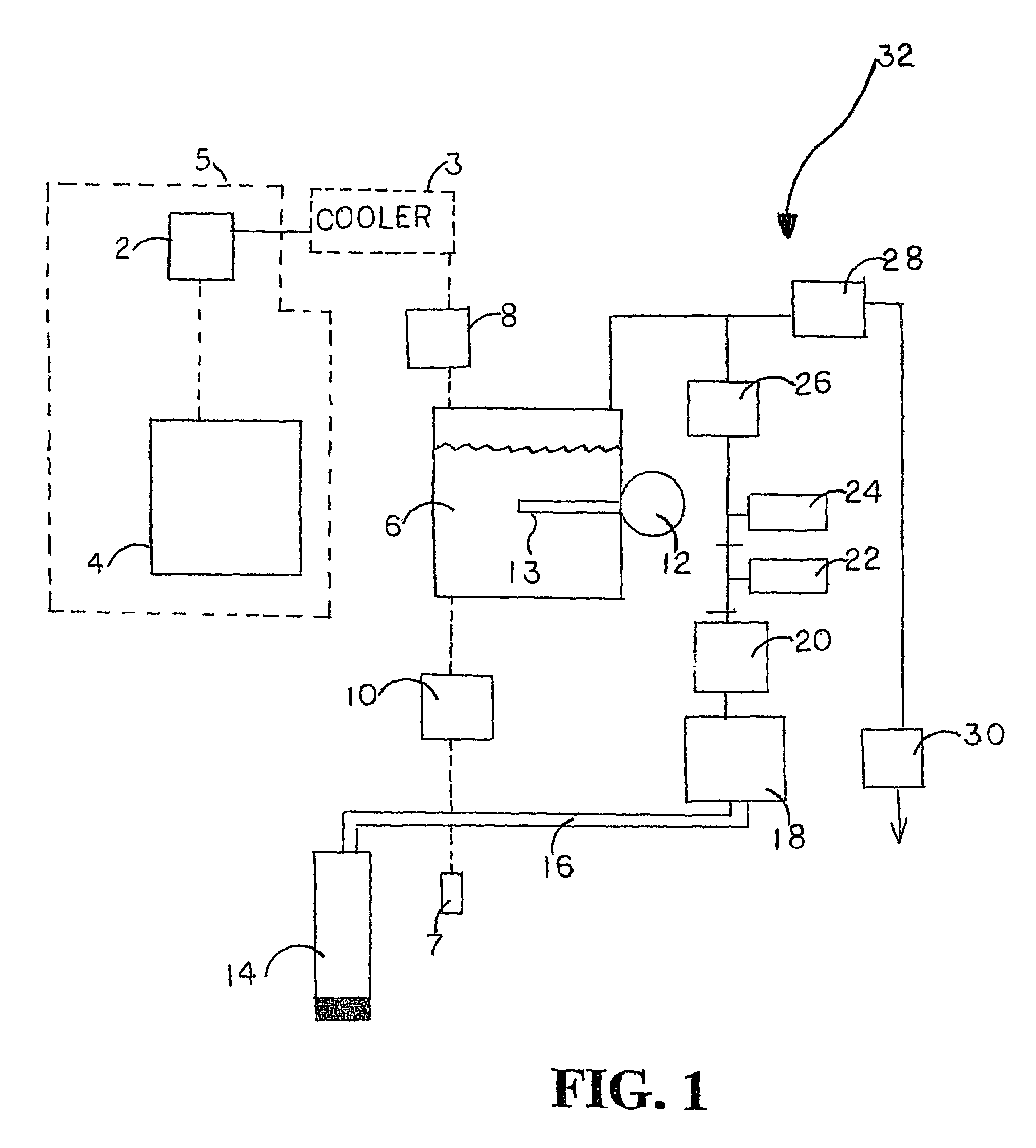
[0022]Turning now to FIG. 1, there is shown a block diagram of the carbonation process according to one embodiment of the present invention. The carbonation system and method may be used with existing or originally manufactured water coolers or other beverage dispensers or in other applications as desired. The system allows existing water coolers to be easily retrofitted to allow selective carbonation. Similarly, the system could be used with other liquid dispensers in a similar fashion. In the example of a water cooler, water from a tank is cooled in the cooler 3 until dispensing is desired. Upon a user requesting a carbonated drink, the system is initiated by a user depressing a switch or another control mechanism. A control system 5 operates the system to cause the opening of a water filling solenoid 8. The control system 5 may comprise an electronic control circuit board 4 and an electrical transformer 2 for conversion of power to control the carbonation system. The solenoid 8 s...


PUM

PropertyMeasurementUnit
Timeaaaaaaaaaa
Timeaaaaaaaaaa
Pressureaaaaaaaaaa

Abstract

The water carbonation method and apparatus of the present invention consists of a square mixer within a carbonated chamber. The mixer is partially filled with water. Carbon dioxide is then added above the level of water. A rotating member attached to the mixing motor then mixes the water and carbon dioxide to from a carbonated solution. Varying the time for which the carbonation operation is carried on may vary the degree of carbonation. After the specified carbonation cycle, excess carbon dioxide is then relieved through an exhaust solenoid and the remaining carbonated solution is released through the dispensing solenoid into a cup.

Description

[0001]This application claims priority from U.S. Provisional Patent Application Ser. No. 60 / 282,232, filed Apr. 6, 2001.TECHNICAL FIELD[0002]The present invention relates to a system and method of carbonating liquids such as in association with a water cooler. More particularly, the present invention is directed to a carbonation system and method that allows effective carbonation to a desired degree.BACKGROUND OF THE INVENTION[0003]Various methods of carbonating water are known in the prior art. One method, involves injecting carbon dioxide into the water. This injection of carbon dioxide forms bubbles that float up through the water. Carbon dioxide in the bubbles is then absorbed into the water. This method has been widely used in relatively small carbonating apparatuses for home use and operable for dispensing carbonated water in quantities sufficient to form one drink. The main problem with this method is that it is only effective if relatively high pressures are used in the carb...

Claims


Application Information

Patent Timeline
IPC IPC(8): B01F3/04A23L2/00B01F1/00B67D1/07B01F13/06B01F15/00B67D1/00G05D23/13G05D23/30
CPCB01F3/04531B01F3/04765B01F3/04808B01F7/04B01F15/00253B01F15/00409B67D1/0057B67D1/0066B67D1/007G05D23/1393G05D23/30B01F13/065B01F15/00123B01F2003/049B01F2215/0477Y10S261/07B67D2210/0006B01F23/233B01F23/2342B01F23/237621B01F23/2362B01F27/70B01F33/71B01F35/20B01F35/22161B01F35/2209B01F23/20
Inventor RONA, GYORGYOSCENAS, JANOSNICOL, SCOTT
Owner PRIMO WATER HLDG INC
Why Eureka
Try Eureka