
Lighting assembly

a technology of assembly and light, applied in the direction of lighting and heating apparatus, lighting support devices, instruments, etc., can solve the problems of many types of more complex controls, and achieve the effect of clean light output and easy identification

Inactive Publication Date: 2006-10-03
IDD AEROSPACE +1
View PDF21 Cites 29 Cited by
  • Summary
  • Abstract
  • Description
  • Claims
  • Application Information

AI Technical Summary

Benefits of technology

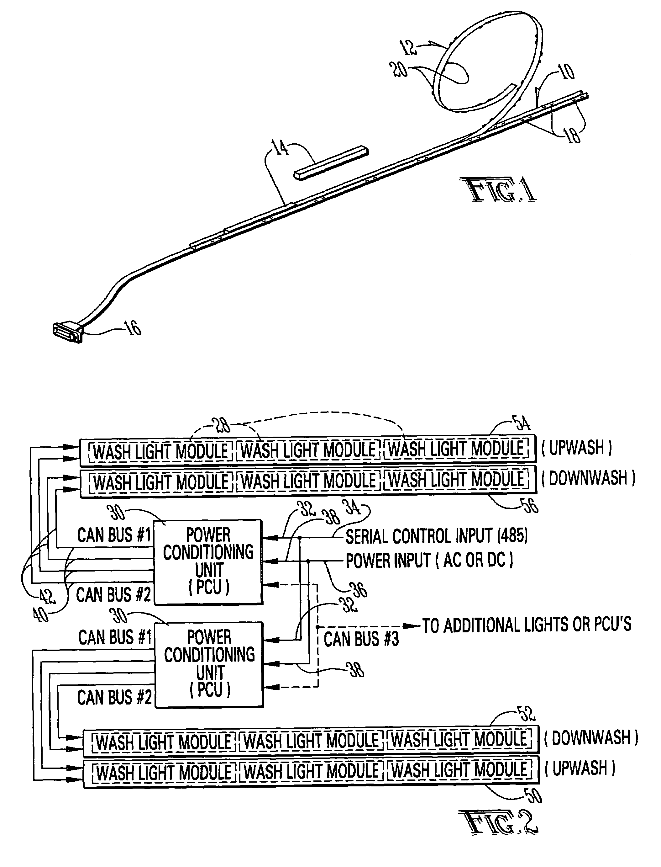
[0010]The present invention offers a number of advantages over existing systems. The use of a single, flexible cable for the distribution of power and data communications to each wash light fixture allows one connection in the aircraft, watercraft, or other main system source to service the entire wash light assembly. Thus the vast bundles of cables, connectors, and related components in existing systems are eliminated. No interconnections between lighting systems in the system are required. This results in considerable savings in lighting system design, installation labor, and overall system weight. In addition, because there are no high-voltage components in the system, and thus no high-voltage wire interconnections, the electromagnetic interference problems created by fluorescent lighting systems are eliminated.
[0029]It is a further object of the present invention to provide a lighting system with diagnostic capabilities whereby problems with an individual lighting fixture may be readily identified.

Problems solved by technology

In addition, many sorts of more complex controls may be employed, such as achieving a spectrum of color or intensity across a cabin section by slightly varying the color or intensity from lighting fixture to lighting fixture along the rail.

Method used


Image

  • Lighting assembly
  • Lighting assembly
  • Lighting assembly

Examples


Embodiment Construction

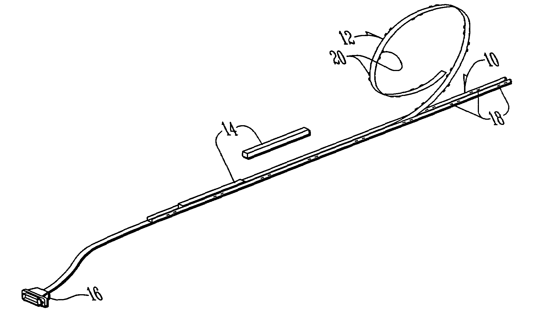
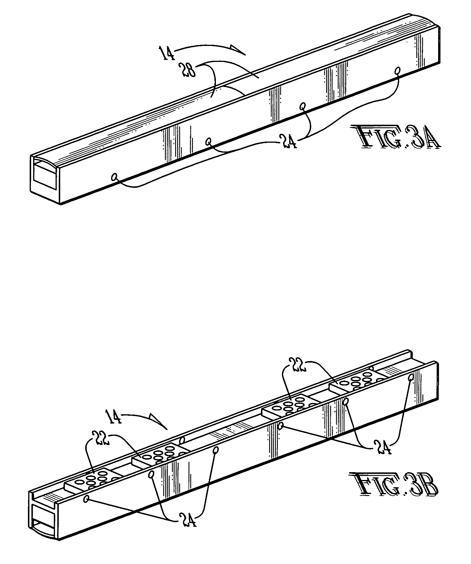
[0035]Referring now to FIG. 1, a preferred embodiment of the present invention for use within the cabin sections of an aircraft or watercraft may now be described. Rail 10 is generally of an elongated, U-shaped design, and is shaped so as to receive cable 12 and lighting fixtures 14. Rail 10 is preferably formed of stainless steel, but may alternatively be formed of any other sufficiently strong and rigid metal or other material in order to provide a strong and durable attachment point for the lighting system within the cabin of an aircraft or watercraft. Stainless steel is the preferred material because its strength reduces the possibility of damage created by pressure and bending of components during installation and maintenance, or when bumped or struck by persons within the cabin during routine use of the craft. In a preferred embodiment, each rail 10 is manufactured to a length of 24 inches, but may be cut to length as needed in the field, preferably in increments to match the ...


PUM


Abstract

A lighting assembly that is modular and highly configurable is disclosed. The assembly consists of one or more light fixtures that are fitted into a mounting rail. A flat, flexible cable lies within the rail and makes contact with the light fixtures through spring-loaded connectors. A power conditioning unit supplies power to the lighting assembly. The lighting assembly may be assembled and maintained with a minimum of tools, and is adaptable to a wide variety of environments and lighting design options.

Description

CROSS-REFERENCE TO RELATED APPLICATIONS[0001]The present application claims the benefit of U.S. provisional patent applications Ser. Nos. 60 / 455,269, entitled “Spectrally Calibratable Multi-Element RGB LED Light Source”; 60 / 455,129, entitled “Indirect Lighting System Architecture and Implementation”; 60 / 455,126, entitled “Anisotropic Etching of Silicon Wafer Materials to Create Micro-Reflector Cavities for LED Die”; and 60 / 455,127, entitled “Micro-Strip-Line Signal and Power Buss Flexible Cable and Method of Using Same,” each of which was filed on Mar. 17, 2003, and for each of which the inventor is Michael A. Halter. The present application is further related to the three co-pending applications filed on even date herewith entitled “Spectrally Calibratable Multi-Element RGB LED Light Source,”“Anisotropic Etching of Silicon Wafer Materials to Create Micro-Reflector Cavities for LED Die,” and “Micro-Strip-Line Signal and Power Bus Flexible Cable and Method of Using Same,” the invento...

Claims


Application Information

Patent Timeline
IPC IPC(8): F21V21/00H01L25/075H05B44/00
CPCH01L25/0753H05B33/0803H01L2924/0002H01L2924/00H05B45/30
Inventor HALTER, MICHAEL A.
Owner IDD AEROSPACE
Learn More