
Water pump for cooling engine

a technology for water pumps and engines, which is applied in the direction of liquid fuel engines, vessel construction, marine propulsion, etc., can solve the problems of unnecessary work to provide a level difference on the outer circumferential surface of the portion on the impeller side of the rotational shaft, and achieve the effect of enhancing the reliability of mounting strength of the impeller and avoiding an increase in costs

Active Publication Date: 2006-10-03
HONDA MOTOR CO LTD
View PDF4 Cites 57 Cited by
  • Summary
  • Abstract
  • Description
  • Claims
  • Application Information

AI Technical Summary

Benefits of technology

[0007]The present invention has been accomplished in view of the foregoing. It is an object of the invention to provide a water pump for cooling an engine for enhancing the reliability of mounting strength of an impeller to a rotational shaft while avoiding an increase in costs.
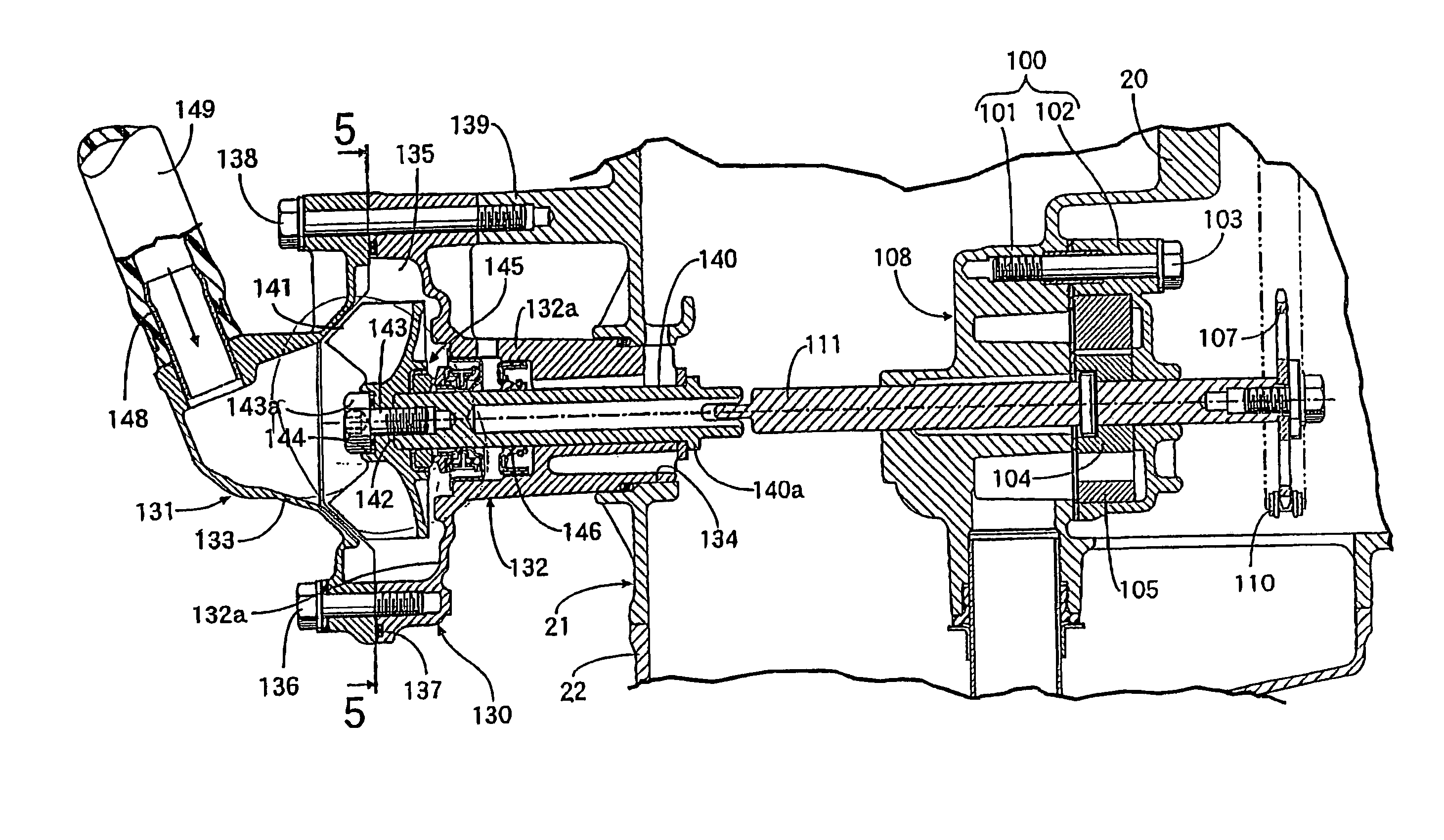
[0009]According to the structure of the present invention as described above, the end of the rotational shaft is fastened to the impeller in the state that is fitted in the fitting recess in the central portion of the impeller. Therefore, the bending load is exerted on the fitting portion of the rotational shaft and the impeller so as to prevent the bolt from being applied with the bending load. Further, since at least the outer circumferential surface on the impeller side of the rotational shaft is formed to be straight without a difference in level, the rotational shaft is relatively large in diameter at the fitting portion, and the reliance of the mounting strength of the impeller can be enhanced without making the rotational shaft itself larger in size. Thus, changes or modifications with respect to other parts constituting the water pump are unnecessary; and an increase in costs can be avoided. Moreover, the work necessary to provide a difference in the level on the outer circumferential surface of the portion on the impeller side of the rotational shaft is unnecessary. This also results in a reduction in the costs of production.
[0010]Further, in the present invention in the central portion of the impeller an engaging recess for fitting an enlarged diameter head portion of the bolt relatively unrotatably is provided and faces opposite to the fitting recess. The rotational direction of the rotational shaft and the impeller is set to the direction in which the bolt is further tightened by the resistance that the impeller receives from the cooling liquid within the pump housing. According to this construction as described above, even if the bolt should be loosened, the bolt is further tightened by the rotation of the impeller. Therefore, positive fastening of the bolt to the rotational shaft, that is, positive fastening of the impeller to the rotational shaft can be maintained.

Problems solved by technology

Moreover, the work necessary to provide a difference in the level on the outer circumferential surface of the portion on the impeller side of the rotational shaft is unnecessary.

Method used


Image

  • Water pump for cooling engine
  • Water pump for cooling engine
  • Water pump for cooling engine

Examples


Embodiment Construction

[0018]The form of carrying out the invention will be described hereinafter on the basis of one embodiment of the present invention shown in the accompanying drawings.

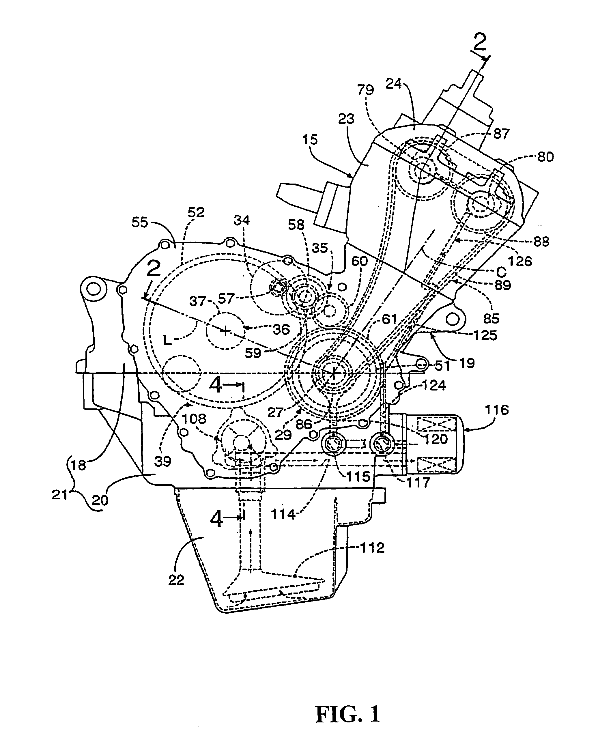
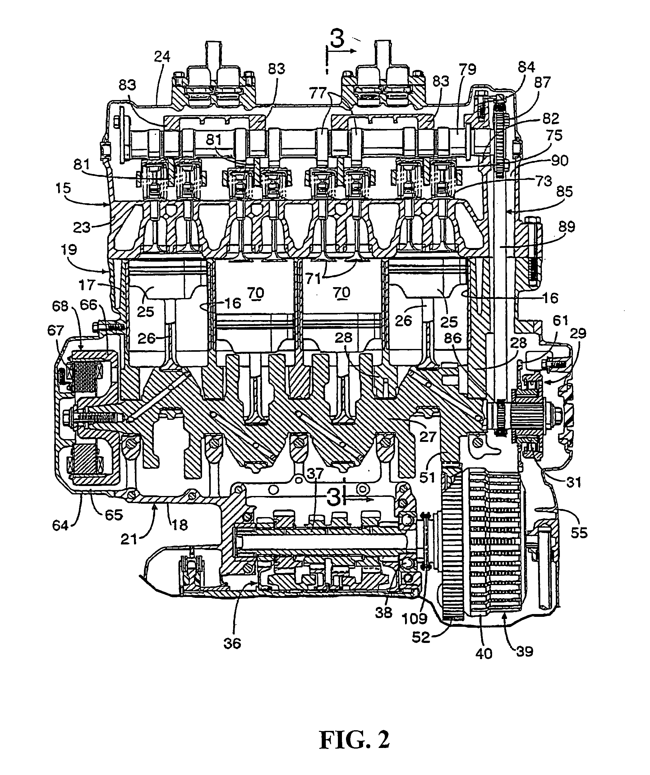
[0019]Referring to FIGS. 1 and 2, a series 4-cylinder engine is mounted, for example, on a motorcycle. An engine body 15 having a forward-upwardly inclined cylinder axis C includes a cylinder block 19 integrally having a cylinder portion 17 provided with four cylinder bores 16 . . . disposed in series and an upper case portion 18 arranged under the cylinder portion 17. A lower case 20 is provided which cooperates with the upper case portion 18 to constitute a crankcase 21 that is connected to a lower part of the cylinder block 19. An oil pan 22 is connected to the lower part of the lower case 20, more specifically to the lower part of the crankcase 21. A cylinder head 23 is connected to an upper part of the cylinder block 19. A head cover 24 is connected to the upper part of the cylinder head 23.

[0020]Pistons 25 . . . a...


PUM


Abstract

A water pump for cooling an engine in which an impeller accommodated in a pump housing provided on an engine body is mounted on an end of a rotational shaft rotatably supported on the pump housing for enhancing the reliability of the mounting strength of the impeller while avoiding an increase in cost. A fitting recess for fitting an end of the rotational shaft having an outer circumferential surface which is straight in an axial direction at least in a portion on the impeller side is provided in a central portion of the impeller. A bolt inserted into the central portion of the impeller is threaded in a coaxial direction with the end of the rotational shaft in a state that is fitted in the fitting recess.

Description

CROSS-REFERENCE TO RELATED APPLICATIONS[0001]The present application claims priority under 35 USC 119 to Japanese Patent Application No. 2003-081930 filed on Mar. 25, 2003 the entire contents thereof is hereby incorporated by reference.BACKGROUND OF THE INVENTION[0002]1. Field of the Invention[0003]The present invention relates to an improvement in a water pump for cooling an engine in which an impeller accommodated in a pump housing provided on an engine body is mounted on an end of a rotational shaft supported rotatably on the pump housing.[0004]2. Description of Background Art[0005]A water pump for cooling an engine having a male thread threaded on the outer circumference of one end of a rotational shaft and mounted relative to a central portion of an impeller to thereby mount the impeller on the end of the rotational shaft has been known, for example, in Japanese Patent Laid-Open No. 2000-88056.[0006]A reaction generated by receiving fluid resistance caused by the cooling liquid...

Claims


Application Information

Patent Timeline
IPC IPC(8): F04D29/36F01D5/00F01P5/04F01P5/10F04D29/22F16F15/26
CPCF01P5/10F04D29/20
Inventor OSHITA, TOHRUSUZUKI, TOSHIMITSU
Owner HONDA MOTOR CO LTD
Learn More