Adjustable thermal scanning system and method

a technology of thermal scanning and adjustment, applied in the field of medical diagnostic equipment, can solve the problems of patient's skin temperature changing after thermal scanning, and achieve the effect of convenient us

Inactive Publication Date: 2006-10-03
GENTEMPO PATRICK +1
View PDF26 Cites 8 Cited by
  • Summary
  • Abstract
  • Description
  • Claims
  • Application Information

AI Technical Summary

Benefits of technology

[0013]Thus, a need exists for a simple, easy to use, hand-held thermal scanning device which is adaptable for use with patients of various sizes. Moreover, a need exists for a system which accurately correlates temperature readings with the location along the patient's spine from which the reading is taken.

Problems solved by technology

One disadvantage of repeating the thermal scan is that the patient's skin temperature changes after the initial scan, in part due to contact between the scanner and the skin surrounding the spine.
The preferred thermal scanning device minimizes repeat scans, a drawback commonly associated with a time-dependent thermal scanning device.

Method used


Image

  • Adjustable thermal scanning system and method
  • Adjustable thermal scanning system and method
  • Adjustable thermal scanning system and method

Examples


Embodiment Construction

[0035]The present invention relates to a thermal scanning system, device and method. In one embodiment of the thermal scanning system, there are two types of scanning and assessment methods: (1) rolling thermal scanning; and (2) segmental thermal scanning.

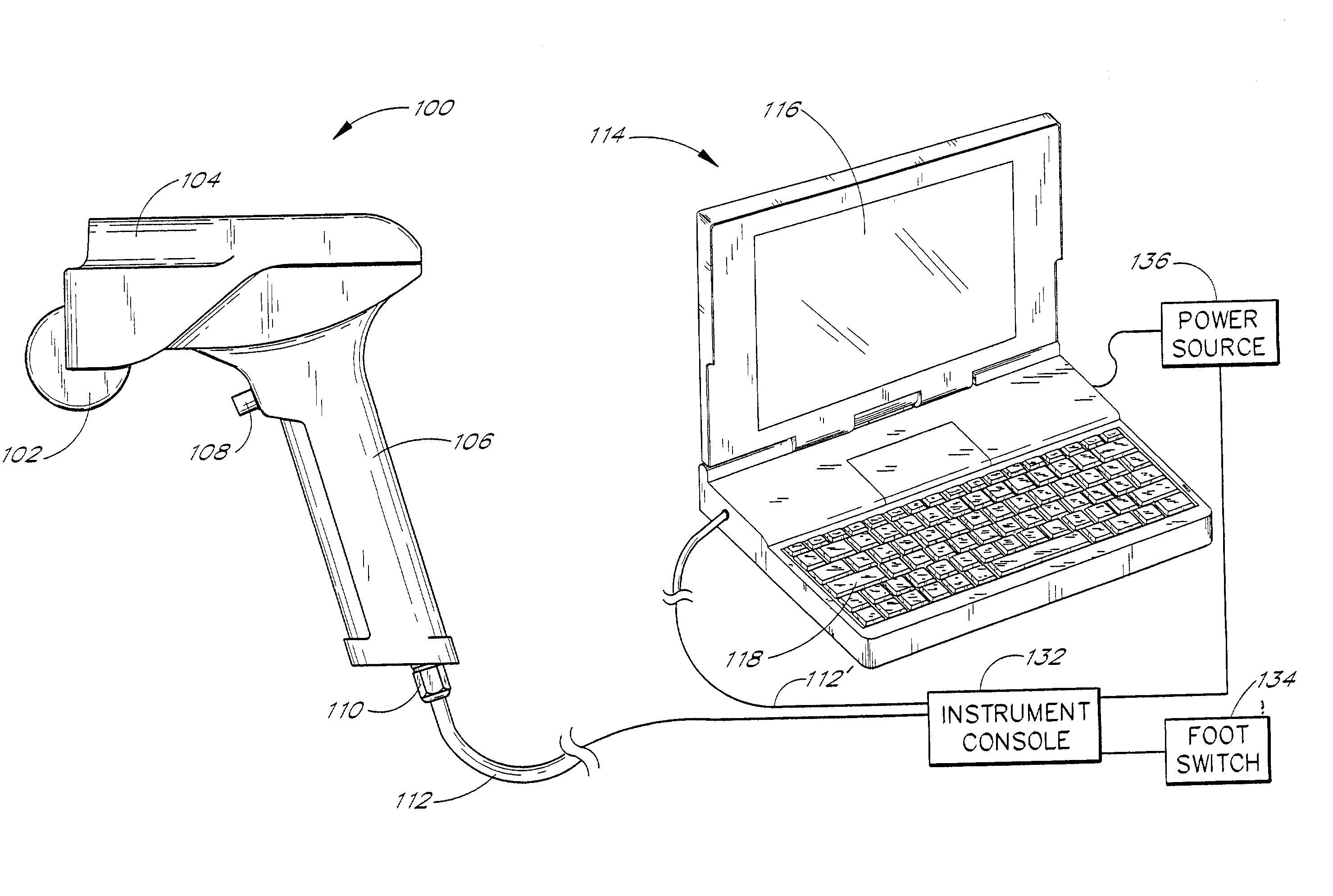
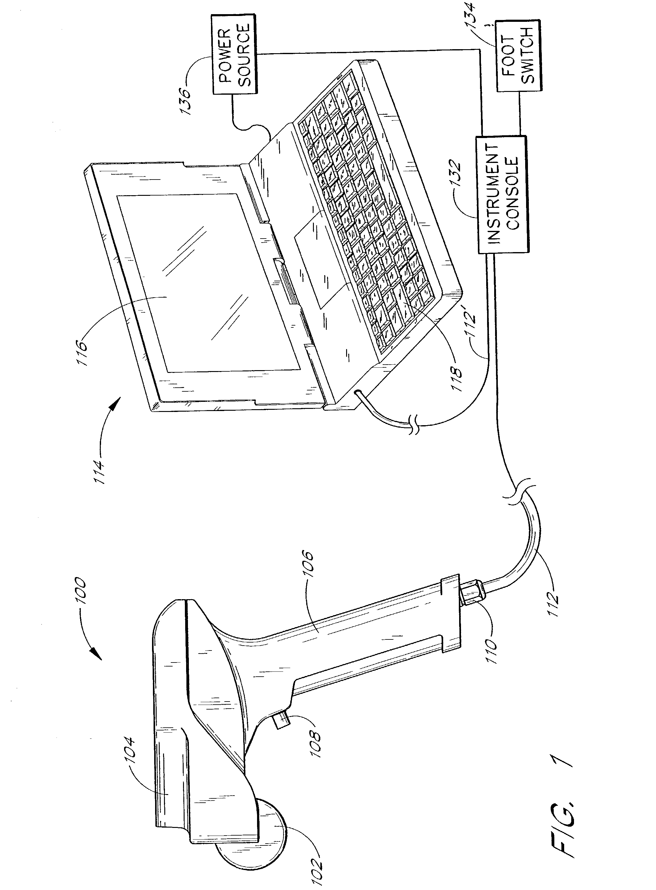
[0036]FIG. 1 illustrates one embodiment of a thermal scanning system that comprises a handheld thermal scanning device or paddle 100, a computer 114, an instrument console 132 and a foot switch 134. The thermal scanning device 100 is coupled to the instrument console 132 via a cable 112. The instrument console 132 is coupled to the computer 114 via a cable 112′. Specifically, one end of the cable 112′ is coupled to a PC RS232 connector of the instrument console 132 and the other end of the cable 112′ is coupled to coupled to a 9-pin serial port, a 25-pin serial port or some other suitable port on the computer 114. The instrument console 132 is also coupled to a foot switch 143. Both the computer 114 and the instrument console 132 m...


PUM


Abstract

A thermal scanning system and method. The thermal scanning system comprises a handheld thermal scanning device with wheels and three infrared sensors that are spaced to scan skin temperature on opposite sides of patient spinal columns of different sizes. Two out of the three sensors are selected for a particular patient, and the wheels are adjustable to accommodate the two selected sensors. The handheld device further calculates the distance traveled by the wheels by measuring the rotation of the wheels. The device has a trigger that allows a user to annotate the location of various anatomical landmarks, such as particular regions of a patient's spinal column. The device is adapted to take discrete temperature readings or rolling temperature readings. The thermal scanning system provides graphical displays and data analysis of the temperature readings from the sensors.

Description

RELATED CASE[0001]This is a continuation application of U.S. patent application Ser. No. 09 / 661,712, filed Sep. 14, 2000 now U.S. Pat. No. 6,440,084, in the names of Patrick Gentempo and Lee Brody, entitled “Thermal Scanning System and Method,” which has been allowed. U.S. patent application Ser. No. 09 / 661,712 is hereby incorporated herein by reference.BACKGROUND OF THE INVENTION[0002]1. Field of the Invention[0003]The present invention relates to medical diagnostic equipment, and in particular to a thermal scanning system and method.[0004]2. Description of the Related Art[0005]Chiropractors and other health care professionals have previously used hand-held devices to measure skin temperature at a variety of locations along a patient's spinal column. The purpose of taking such measurements is to monitor skin temperatures surrounding the spine. Alterations in skin temperature readings may be indicative of abnormal autonomic nervous system activity, which in turn may indicate a spina...

Claims


Application Information

Patent Timeline
Patent Type & Authority Patents(United States)
IPC IPC(8): A61B5/00A61B5/01A61B5/107
CPCA61B5/01A61B5/1072
Inventor GENTEMPO, PATRICKBRODY, LEE
Owner GENTEMPO PATRICK
Why Eureka
Try Eureka