Receiving coil for nuclear magnetic resonance imaging apparatus for spinal column images

a nuclear magnetic resonance imaging and spinal column technology, applied in the direction of superconducting magnets/coils, using reradiation, magnetic materials, etc., can solve the problems of loss of sensitivity in the deep areas of the part under examination, poor contribution to the coil field in some points inside the area under examination, and inability to consider, etc., to achieve easy integration with further turns, simple and cost-effective construction, and increase sensitivity

Active Publication Date: 2006-10-03
ESAOTE
View PDF11 Cites 4 Cited by
  • Summary
  • Abstract
  • Description
  • Claims
  • Application Information

AI Technical Summary

Benefits of technology

[0008]The advantages of the embodiment are that the coil is simple and cost effective to construct and it can be easily integrated with further turns in order to increase its sensitivity. Indeed, it's very easy to manufacture and to handle the rectangular turns. The simplicity of turns allows also to provide a modular construction allowing the progressive addition of turns to a coil having a base number of turns, namely the at least two turns constituting the two detecting wires.
[0010]Since spinal column images are generally imaged with the patient at least partially laid on an examination table, the simplicity of the depicted coil and the reduced dimensions allow to integrate the aforementioned receiving coil inside the examination table supporting the patient. In this embodiment, the side provided with the two detecting wires extends at or under the supporting bench of the apparatus, while the remaining part of the coil is embedded inside the examination table structure that generally has a fair thickness in order to allow driving of various positioning and adjusting devices to pass through it.
[0011]This configuration reduces the detection of artifacts and electromagnetic noise coming from patient areas that are not of interest, i.e. not from the spinal column anatomic district. Moreover, the arrangement of the useful detecting conductors as well as of the whole coil are geometrically adapted to the geometry or morphology of the spinal column. Moreover the overall arrangement of the coil conductors is extremely simplified and it allows an easy integration of the number of the useful detecting conductors for improving or varying the sensitivity.
[0012]However, the re-closing wires parallel to the useful detecting conductors of the resonance signals provided at a certain distance from the bench supporting the patient, can cause a contrast effect of the current induced in the detecting conductors on the field useful for image acquisition. This can cause a loss in sensitivity in the deep areas of the part under examination, i.e. the ones that are more distant from the conductors. Hence, the direction of the current flow in the re-closing wires is opposite to that of the detecting conductors and so the field generated by the re-closing wires is opposite to that of the detecting conductors.
[0014]The shield, for example composed of copper, produces a reflection of the detecting conductors and of the re-closing wires, which reflected image has current flows, inside the reflections of the re-closing wires, that are opposed to the ones of the re-closing wires, eliminating or drastically reducing the contribution to the magnetic field of the re-closing wires.

Problems solved by technology

This can cause a loss in sensitivity in the deep areas of the part under examination, i.e. the ones that are more distant from the conductors.
The reflections made by the reflection conductor shield of the detecting conductors have a great distance from the location of the detecting wires and the contribution to the coil field in some points inside the area under examination is poor and it can be not considered.

Method used


Image

  • Receiving coil for nuclear magnetic resonance imaging apparatus for spinal column images
  • Receiving coil for nuclear magnetic resonance imaging apparatus for spinal column images
  • Receiving coil for nuclear magnetic resonance imaging apparatus for spinal column images

Examples


Embodiment Construction

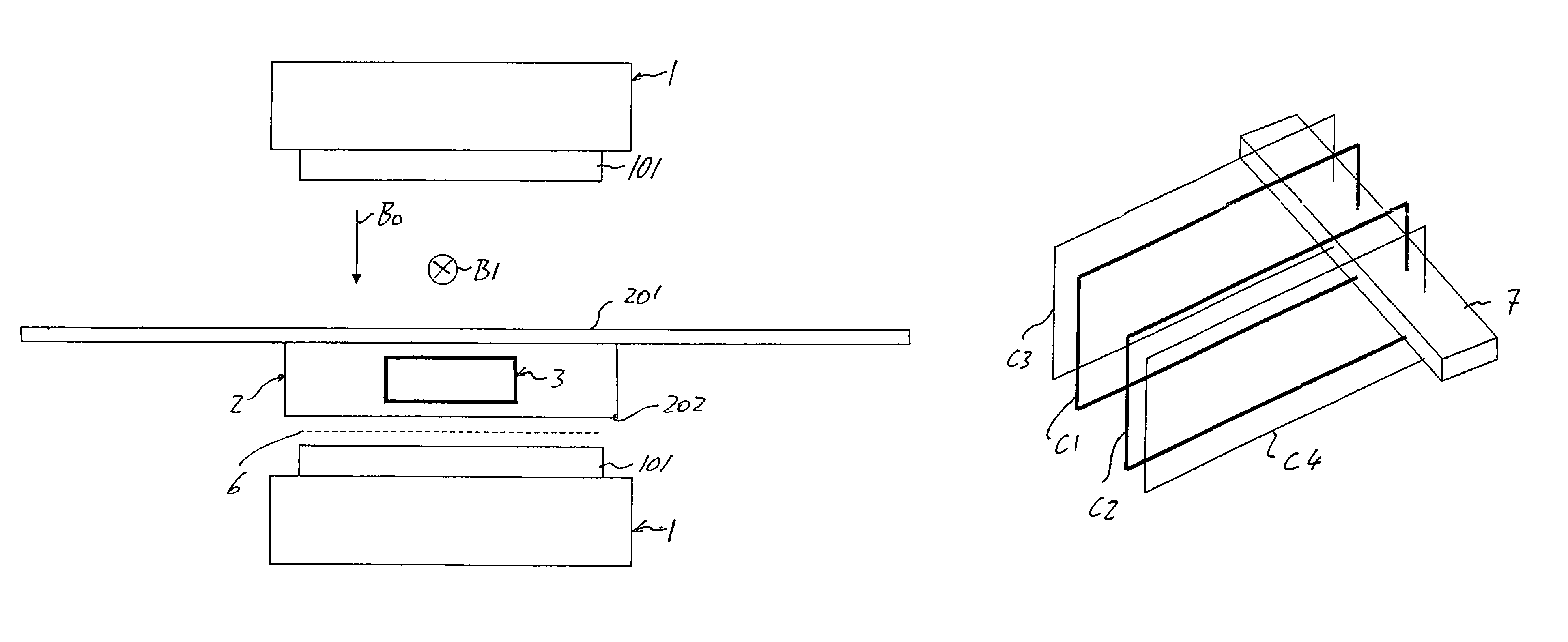
[0025]In FIG. 5 an MRI apparatus is schematically shown which is particularly dedicated to imaging the spine or part thereof. The apparatus includes a magnetic structure 1 for generating a vertical static magnetic field B0 between two poles 101. The static magnetic field is indicated by the arrow B0. An examination table 2 for supporting the patient includes an horizontal supporting bench 201 for the patient that has to be laid supine on said bench.

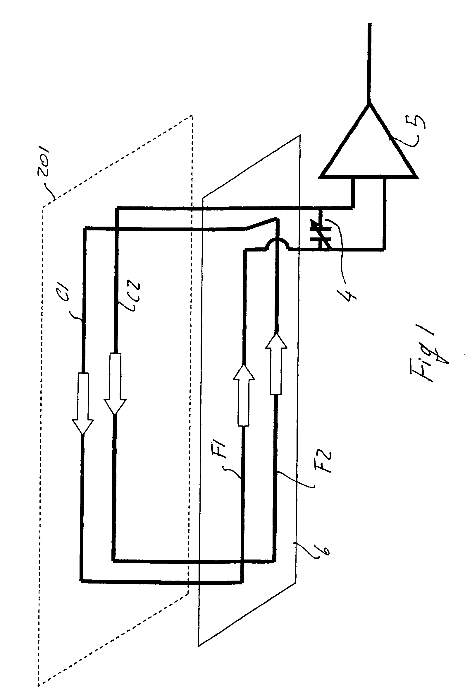
[0026]The supporting bench 201 is supported by a bearing structure 202 that has a certain thickness and wherein a chamber can be obtained for accommodating a receiving coil 3. As it will result with reference to the following description, the receiving coil 3 is manufactured so as to generate a field indicated at B1 and oriented in the horizontal plane and having a perpendicular direction with respect to the static field B0. The field B1 that is perpendicular to the drawing sheet is indicated by the star B1 in FIG. 5. In the same figure, ...


PUM

PropertyMeasurementUnit
static magnetic fieldaaaaaaaaaa
lengthaaaaaaaaaa
widthaaaaaaaaaa

Abstract

Receiving coil for nuclear magnetic resonance imaging apparatus for spinal column images, where the apparatus has a supporting bench of the patient and an element for generating a static magnetic field perpendicularly oriented with respect to the supporting bench of the patient. The receiving coil is provided with at least two conductors useful for the detection extending in the direction of the positioning of the longitudinal extension of the spinal column and in the supporting bench or in a bench parallel to the supporting bench of the patient and have a length that is enough to cover approximately the anatomic district of the spinal column or a part of interest thereof, the distance of the two conductors being in the order of magnitude of the average width of the spinal columns and the two conductors being connected in such a way to have a coherent flowing direction of current.

Description

FIELD OF THE INVENTION[0001]The present invention relates to nuclear magnetic resonance imaging apparatuses, and particularly to a receiving coil for a nuclear magnetic resonance imaging apparatus for spinal column images.DESCRIPTION OF THE RELATED ART[0002]Nuclear magnetic resonance imaging apparatus for spinal column images provided with a receiving coil are known. These apparatus use horizontal field flat coils in conjunction with a vertical static magnetic field, where the spinal column being imaged is arranged on an horizontal bench. This configuration of the arrangement between the receiving coil and the magnetic field of the nuclear magnetic resonance imaging apparatus is referred to as the “butterfly” configuration. However, because the spinal column has a long and narrow structure, this configuration also detects noise and artifact signals coming from body areas under examination which are devoid of interest.[0003]Other types of receiving coils for nuclear magnetic resonanc...

Claims


Application Information

Patent Timeline
Patent Type & Authority Patents(United States)
IPC IPC(8): H01F7/00G01R33/34
CPCG01R33/34046G01R33/34053G01R33/341G01R33/34061
Inventor VITTORIO, VITI
Owner ESAOTE
Why Eureka
Try Eureka