Image processing system optical shifting mechanism

a technology of optical shifting and image processing, applied in the field of image processing system, can solve the problems of blur filter significantly limiting the capacity of the detection system to produce sharp images, requiring matching electronically controlled devices, and aliasing distortions or undersampling of such systems

Inactive Publication Date: 2006-10-03
SHARP KK
View PDF44 Cites 18 Cited by
  • Summary
  • Abstract
  • Description
  • Claims
  • Application Information

AI Technical Summary

Problems solved by technology

In the design of optical detection and acquisition systems, a significant problem has been the susceptibility of such systems to aliasing distortions or undersampling artifacts.
A substantial difficulty with such designs, however, is that the blur filter significantly limits the capacity of the detection system to produce sharp images, i.e., anti-aliasing and retaining sharpness are competing goals.
Unfortunately, the crystals need to have perfectly matched characteristics and the dual electronic controls need control signals that exactly correspond electrically for the device to operate properly.
's disadvantage of requiring matched electronically controlled devices.
Unfortunately, this dual birefringent crystal device only enhances sharpness along a single dimension.
Moreover, the simultaneous beams limit the capacity of the device for sharply resolving finely detailed images.
The moving parts decrease reliability, require excessive space to operate, are cumbersome, are bulky, tend to get out of alignment, and are not reliable.
Moreover, the simultaneous beams limit the capacity of the device for sharply resolving finely detailed images.
Unfortunately, each output beam is derived from light entering multiple input locations.
This results in a loss of information and a resulting reduction in sharpness enhancement capacity.

Method used


Image

  • Image processing system optical shifting mechanism
  • Image processing system optical shifting mechanism
  • Image processing system optical shifting mechanism

Examples


Embodiment Construction

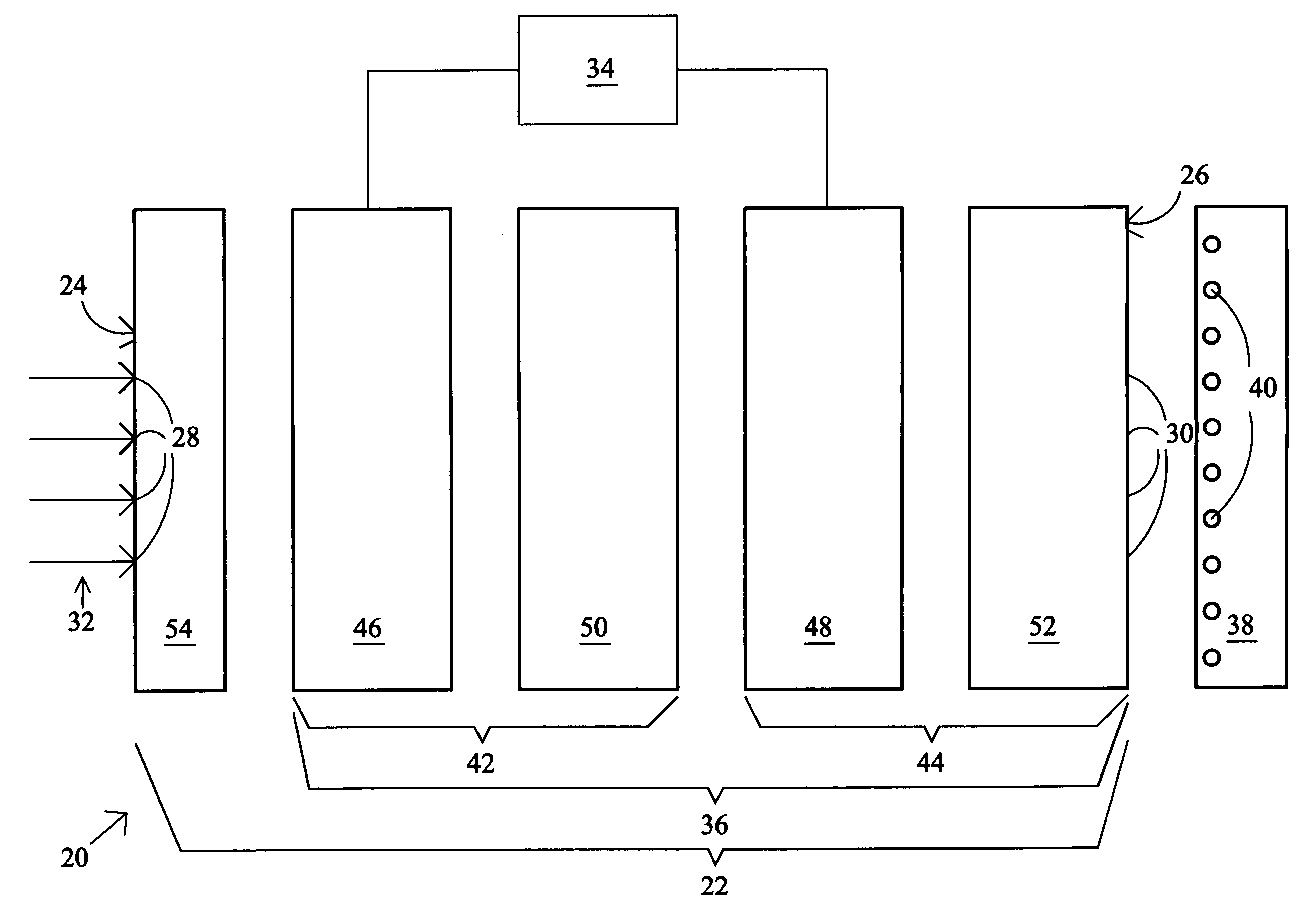
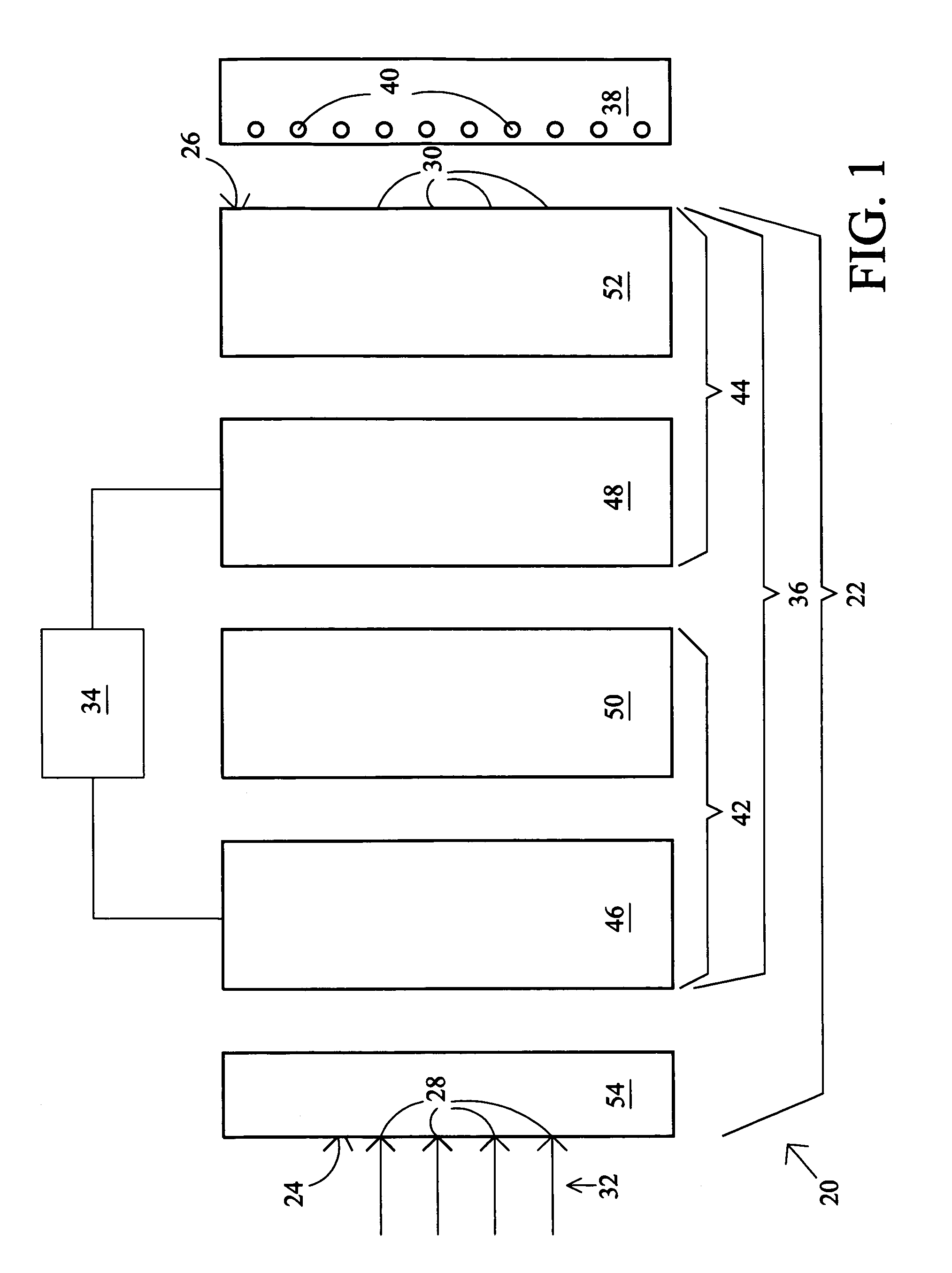
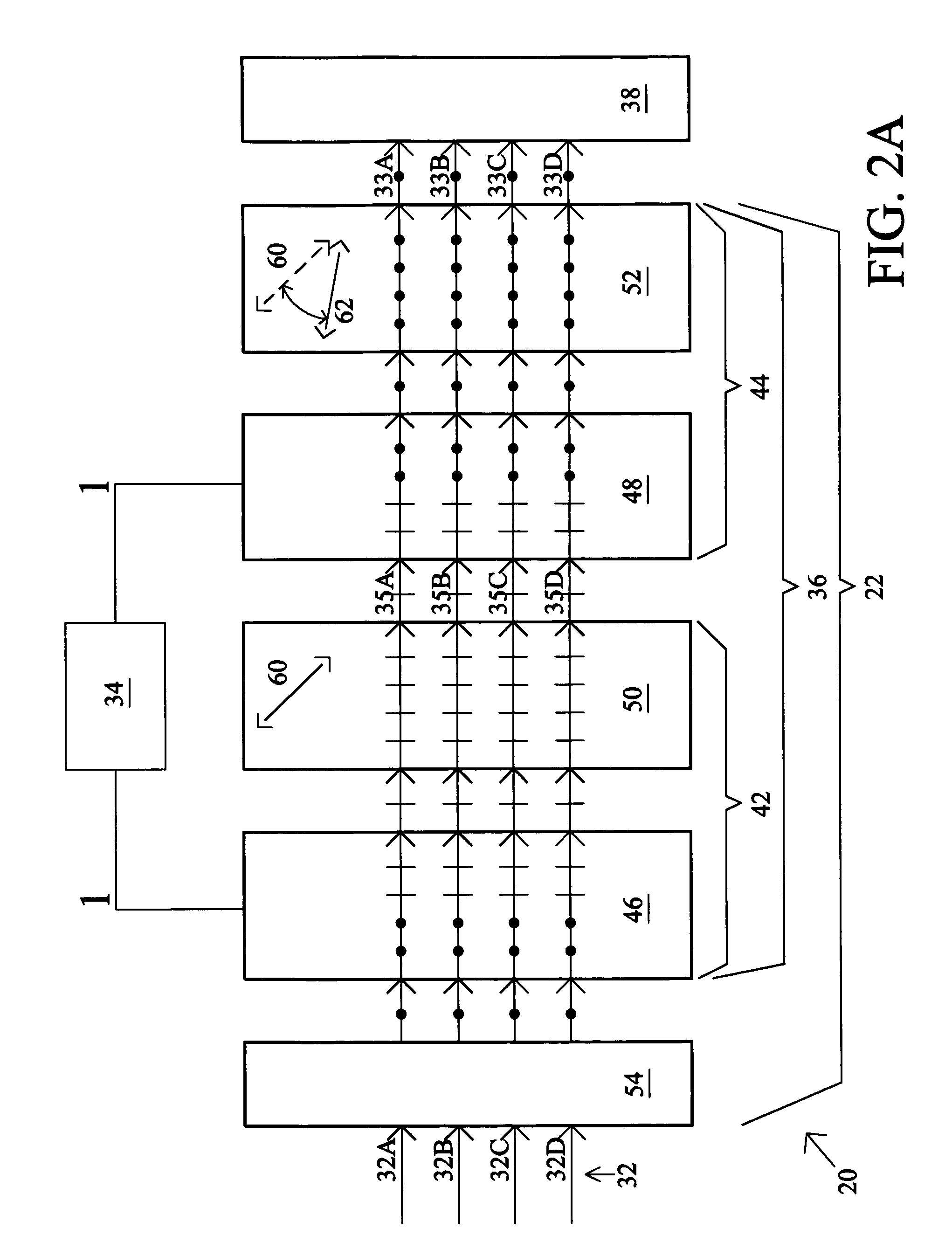
[0023]FIG. 1 depicts an image processing system 20 that includes an optical assembly 22 having an input surface 24 and an output surface 26. The input and output surfaces 24, 26 define a plurality of continuous input and output positions 28 and 30, respectively, for individual light rays 32 of an image to enter (light rays 32) and exit (light rays 33, see FIGS. 2A–5A), respectively, the optical assembly 22. In general, the light rays 32 are preferably randomly polarized light. However, any type of polarized light may be used, if desired. The image processing system 20 includes a mode-controlling device 34 that operates a light shifting apparatus 36 so that a respective one of the light rays 32 incident on a corresponding one of the input positions 28 is selectively shiftable consecutively between different ones of the output positions 30 for projection onto an image sensor 38. The mode-controlling device 34 permits dynamic control of the image processing system 20. The sensor 38 pre...


PUM


Abstract

An image processing system processes light conveying visual pattern information represented by individual light rays. The system includes an optical assembly having an input surface and an output surface. The input and output surfaces define a plurality of input and output positions, respectively, for the light rays to enter and exit, respectively, the assembly. The assembly includes a light-shifting apparatus operable so that a respective one of the light rays entering a respective one of the input positions is selectively shiftable by the apparatus in a first direction and, subsequently, in a second direction angled with respect to the first direction from a preceding one to another of the output positions. The assembly is further operable so that following each shifting operation, a respective one of the light rays transmitted by the assembly from an arbitrarily selected one of the output positions is solely derived from the light received from a single one of the input positions.

Description

BACKGROUND OF THE INVENTION[0001]The present invention relates to an image processing system that may be employed in association with an optical detection and acquisition system, such as a camera, in order to improve the quality of images acquired by the detection and acquisition system.[0002]In the design of optical detection and acquisition systems, a significant problem has been the susceptibility of such systems to aliasing distortions or undersampling artifacts. This effect occurs when a detection system acquires an image having a visual pattern containing high spatial frequency components as, compared to the spatial sampling density of the photoreceptor array employed in the detection system. Thus, if a camera having a solid state array of photosensors is directed at a pattern of alternating dark and light fine stripes, a familiar moire pattern having wavy or flickering lines can distort the resolved image.[0003]It is well known that aliasing distortion can be eliminated by re...

Claims


Application Information

Patent Timeline
Patent Type & Authority Patents(United States)
IPC IPC(8): H04N5/225G02B27/28G02B27/46
CPCG02B27/28G02B27/46H04N5/2254H04N23/55
Inventor HUANG, AUSTIN L.DALY, SCOTTMESSING, DEANSAMPSELL, JEFFREY B.
Owner SHARP KK
Why Eureka
Try Eureka