Projector that displays an image using laser beams

a laser beam and projector technology, applied in the field of projectors, can solve the problems of difficult to reduce speckle noise, unsatisfactory effect of image to be displayed, and inconvenient to use, and achieve the effect of reducing speckle nois

Inactive Publication Date: 2011-01-25
SEIKO EPSON CORP
View PDF23 Cites 1 Cited by
  • Summary
  • Abstract
  • Description
  • Claims
  • Application Information

AI Technical Summary

Benefits of technology

[0006]It is an advantage of some aspects of the invention to provide a projector capable of reducing speckle noise and displaying a high-quality image without imposing any limitation on the types of screen or the like to be used.
[0008]The beam angle of light constituting pixels can be varied in a predetermined angle range by parallel shift of light using the light shifting unit. When light is shifted at a particular position on the projection optical system, only the bean angle can be varied without shift of the image formation position on a screen or the like. In this case, a particular speckle pattern becomes inconspicuous by changing speckle patterns according to variations of the beam angle. Thus, a high-quality image can be displayed with improvement over resolution decrease and reduction of speckle noise. This structure capable of reducing speckle noise by using the components contained in the projector can reduce speckle noise even when combined with an ordinary screen or the like having no particular structure for reducing the speckle noise. Accordingly, the projector in this aspect of the invention achieves speckle noise reduction and high-quality image display when used in combination with any types of screen.
[0011]According to this aspect of the invention, it is preferable that the light shifting unit has a transmission unit which transmits light. In this case, it is preferable that the transmission unit is rotatable around a rotation axis. The light incident angle with respect to the transmission unit can be varied in accordance with rotation of the transmission unit. Thus, shift of light can be achieved by utilizing the simple rotational movement of the transmission unit.
[0012]According to this aspect of the invention, it is preferable that the transmission unit has a plate shape. According to this structure, light can be easily and widely shifted.
[0013]According to this aspect of the invention, it is preferable that the light shifting unit has a polarization converting unit which sequentially converts polarization condition of entering light into first polarized light having a first oscillation direction and a second polarized light having a second oscillation direction substantially orthogonal to the first oscillation direction before the entering light exits. In this case, it is preferable that the first polarized light and the second polarized light supplied from the polarization converting unit are disposed at different positions in the direction substantially perpendicular to the optical axis at the time of exiting from the light shifting unit. Light can be easily controlled by converting the polarization condition. Thus, shift of light is easily and widely achievable by the simplified light control.
[0014]According to this aspect of the invention, it is preferable that the polarization converting unit has a liquid crystal element. According to this structure, the polarization condition of light can be easily converted.

Problems solved by technology

The speckle noise recognized during display of an image has undesirable effect on the image to be displayed, since the audience is dazzled by flickering light produced by the speckle noise.
However, in the structure which attains reduction of speckle noise based on the construction of the screen, speckle noise becomes conspicuous when a screen other than the dedicated screen is employed.
According to the technology in the related art, therefore, it is difficult to reduce speckle noise without imposing any limitation on the types of screen or the like.

Method used


Image

  • Projector that displays an image using laser beams
  • Projector that displays an image using laser beams
  • Projector that displays an image using laser beams

Examples


first embodiment

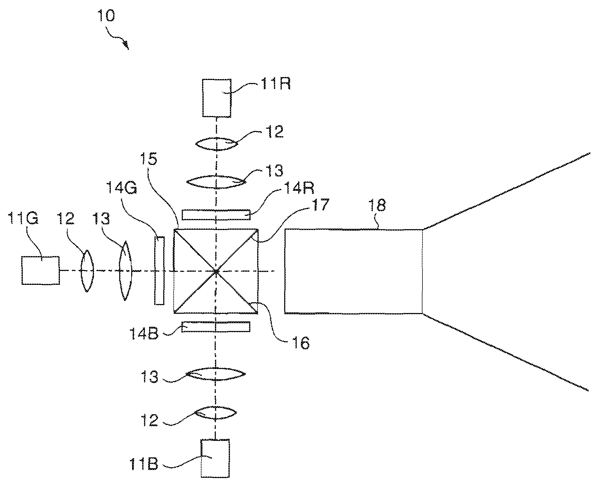
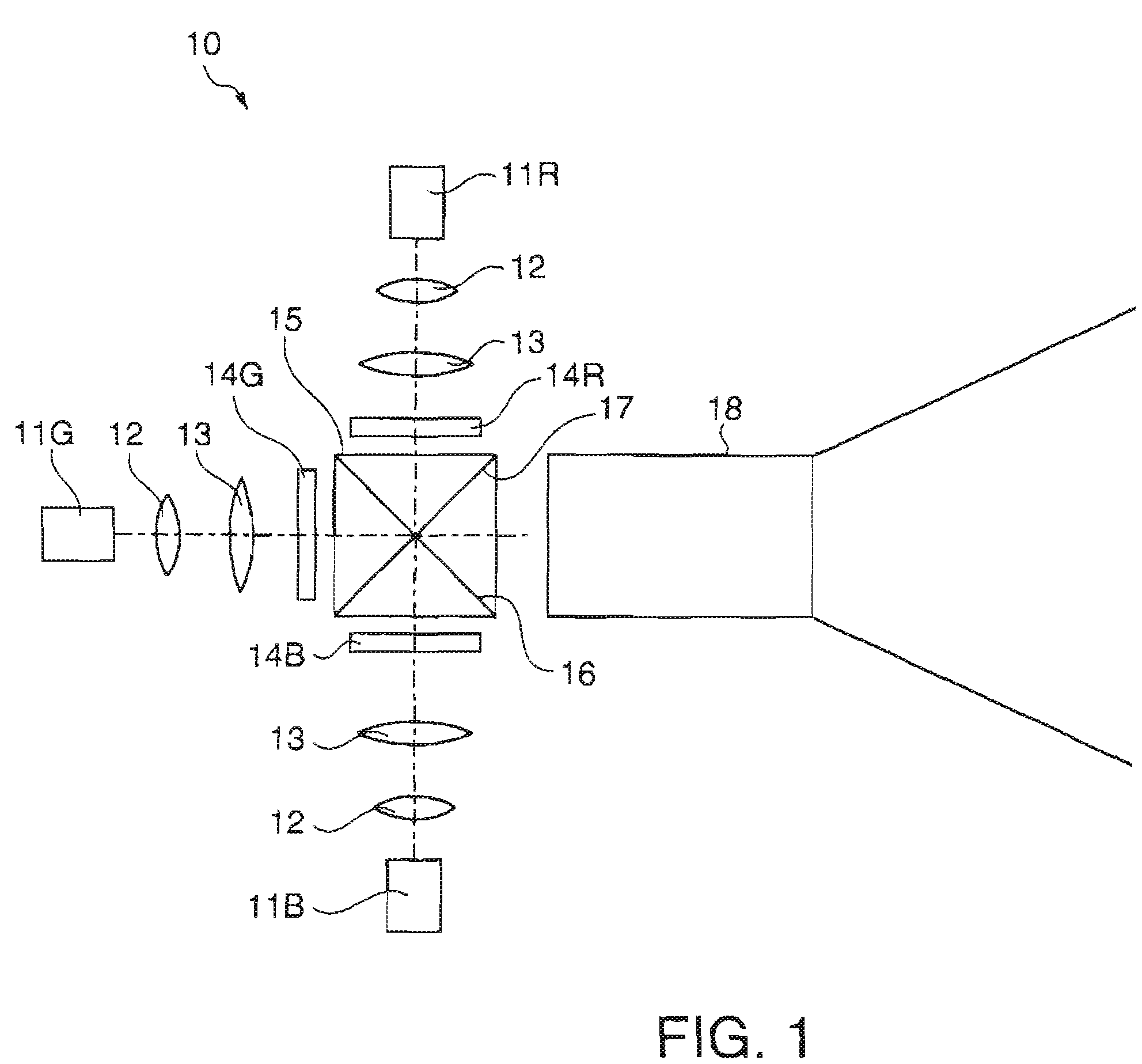
[0028]FIG. 1 schematically illustrates a structure of a projector 10 according to a first embodiment of the invention. The projector 10 is a so-called front projection type projector which supplies light onto a screen 19 and displays an image to be observed created by the reflected light on the screen 19. Each of a light source unit 11R for red (R) light, a light source unit 11G for green (G) light, and a light source unit 11B for blue (B) light is a light source unit for supplying laser beam as coherent light.

[0029]The light source unit 11R for R light is a semiconductor laser for supplying laser beam of R light. A diffusion lens 12 diffuses the laser beam emitted from the light source unit 11R for R light. A field lens 13 collimates the laser beam diffused by the diffusion lens 12 and supplies the collimated laser beam to a spatial light modulating unit 14R for R light. The spatial light modulating unit 14R for R light is a spatial light modulating unit which modulates the R light...

second embodiment

[0048]FIG. 6 schematically illustrates a projection lens 30 according to a second embodiment of the invention. A projection lens 30 in this embodiment can be used in the projector 10 in the first embodiment. The projection lens 30 in this embodiment has a liquid crystal element 31 and a double refraction element 32 in lieu of the transmission unit 25. Similar reference numbers are given to components and parts similar to those in the first embodiment, and the same explanation is not repeated. The liquid crystal element 31 and the double refraction element 32 constitute a light shifting unit provided on the optical path of the projection lens 30.

[0049]The liquid crystal element 31 and the double refraction element 32 are disposed at the position of the stop 23. The liquid crystal element 31 has liquid crystal molecules dispersed in a parallel plate. The liquid crystal element 31 is a polarization converting unit which sequentially converts the polarization condition of entering light...


PUM


Abstract

A projector includes: a light source unit which supplies coherent light; a spatial light modulating unit which modulates the coherent light supplied from the light source unit according to an image signal; a projection optical system which projects light modulated by the spatial light modulating unit; and a light shifting unit disposed on an optical path of the projection optical system to shift light in a direction substantially perpendicular to an optical axis.

Description

BACKGROUND[0001]1. Technical Field[0002]The present invention relates to a projector, and more particularly to a technology of projector which displays an image using laser beams as coherent lights.[0003]2. Related Art[0004]When laser beams as coherent lights are applied to a diffusing surface, coherent patterns called speckle noise containing randomly distributed bright points and dark points appear in some cases. The speckle noise is generated by random coherences between diffused lights at respective points on the diffusing surface. The speckle noise recognized during display of an image has undesirable effect on the image to be displayed, since the audience is dazzled by flickering light produced by the speckle noise. For reducing the speckle noise, a technology which produces oscillation of a screen has been proposed in JP-A-2005-107150, for example. According to this technology, a particular speckle pattern becomes relatively inconspicuous by stacking a plurality of speckle pa...

Claims


Application Information

Patent Timeline
Patent Type & Authority Patents(United States)
IPC IPC(8): G03B21/14
CPCG03B21/14G02B27/48G03B21/208
Inventor ARUGA, SUSUMU
Owner SEIKO EPSON CORP
Why Eureka
Try Eureka