Atomic oscillator, electronic apparatus, and moving object

a technology of electronic equipment and moving objects, applied in the direction of preselected time interval producing apparatus, automatic control, instruments, etc., to achieve the effect of high frequency stability and high reliability

Active Publication Date: 2015-11-24
SEIKO EPSON CORP
View PDF15 Cites 2 Cited by
  • Summary
  • Abstract
  • Description
  • Claims
  • Application Information

AI Technical Summary

Benefits of technology

[0016]According to the atomic oscillator of the application example, a bias current can be automatically set and be stabilized in a vicinity of a minimum point of an absorption band by storing a value of the bias current and a value of the light intensity in the vicinity of the minimum point of the light absorption band of the gas cell in the sweep processing and setting the bias current to a value stored in the sweep processing, comparing the value of the intensity of the light in the state where the bias current is stabilized (locked) with the value stored in the sweep processing in the re-sweep determination processing, and retrying the sweep processing as necessary. Accordingly, it is possible to enhance frequency stability by the atomic oscillator in this application example.
[0037]According to these application examples, it is possible to provide the electronic apparatus and the moving object with high reliability since the atomic oscillator with high frequency stability is provided therein.

Problems solved by technology

However, if a long time (ten years, for example) has passed, there is a case where a bias current value when the amount of light absorption of the gas cell reaches the maximum value (the minimum point of an absorption band) significantly deviates from an initial setting value due to time degradation of the semiconductor laser.

Method used


Image

  • Atomic oscillator, electronic apparatus, and moving object
  • Atomic oscillator, electronic apparatus, and moving object
  • Atomic oscillator, electronic apparatus, and moving object

Examples


first embodiment

1-1. First Embodiment

Configuration of Atomic Oscillator

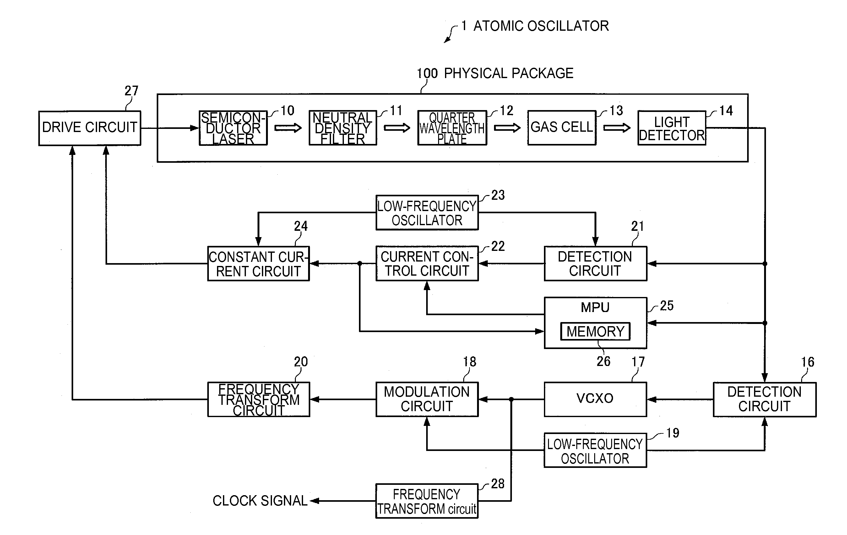
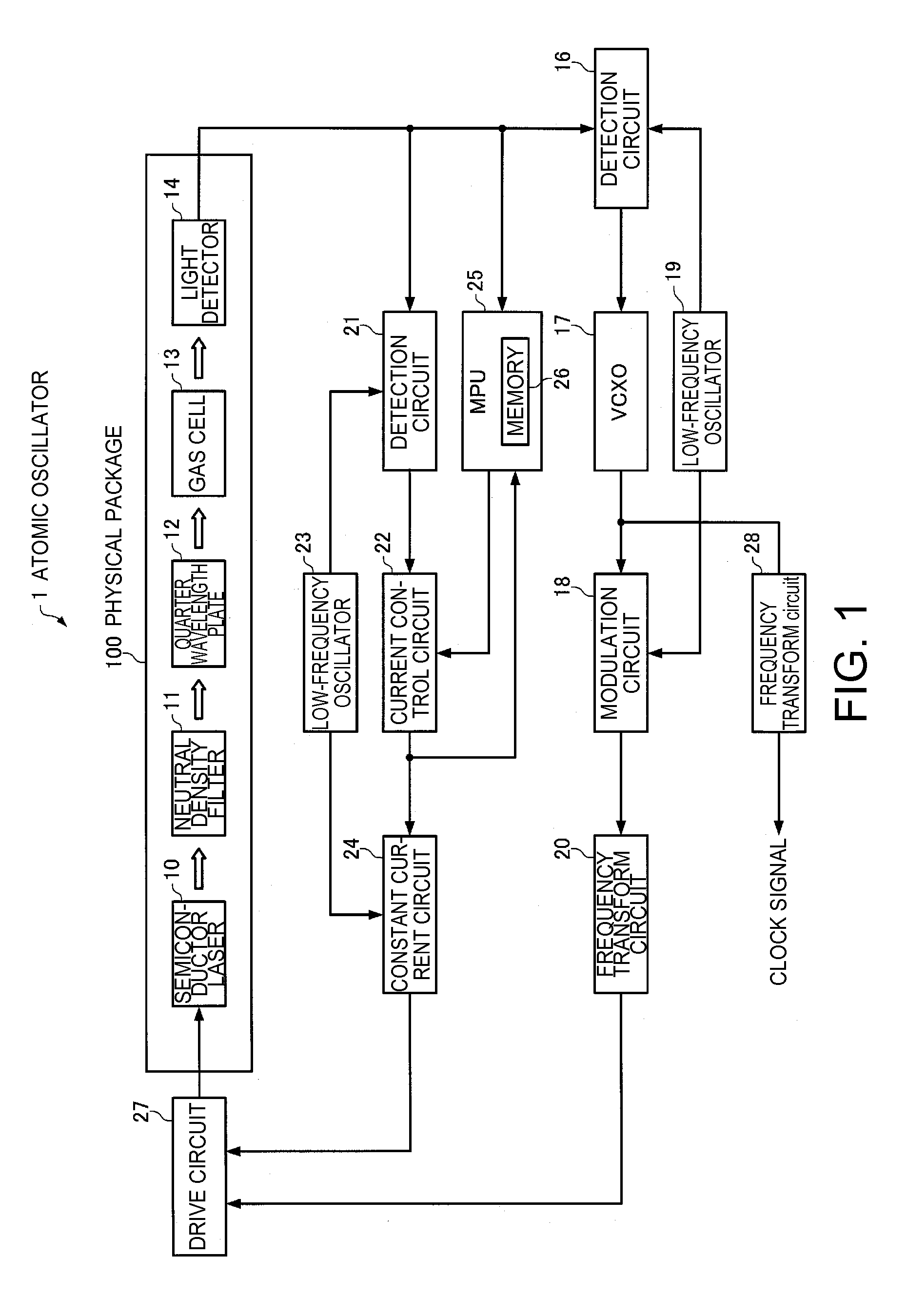
[0054]FIG. 1 is a diagram showing a configuration example of an atomic oscillator according to an embodiment. As shown in FIG. 1, an atomic oscillator 1 according to the first embodiment includes a semiconductor laser 10, a neutral density filter (ND filter) 11, a quarter wavelength plate 12, a gas cell 13, a light detector 14, a detector circuit 16, a voltage controlled crystal oscillator (VCXO) 17, a modulation circuit 18, a low-frequency oscillator 19, a frequency transform circuit 20, a detector circuit 21, a current control circuit 22, a low-frequency oscillator 23, a constant current circuit 24, an MPU 25, a drive circuit 27, and a frequency transform circuit 28. In addition, the atomic oscillator 1 according to the embodiment may have a configuration in which a part of the constituents (respective units) in FIG. 1 is appropriately omitted or changed or a configuration in which other constituents are added thereto.

[0055]Th...

second embodiment

1-2. Second Embodiment

[0108]According to the atomic oscillator 1 of a second embodiment, the MPU 25 determines whether or not it is necessary to change the setting of the bias current before the initial sweep processing in the bias current automatic setting processing and performs the sweep processing and the re-sweep determination processing only when necessary. Since the configuration of the atomic oscillator 1 of the second embodiment is the same as that of the first embodiment (FIG. 1), the depiction and the description thereof will be omitted. In addition, since functions of the respective parts other than the MPU 25 are the same as those in the first embodiment, the description thereof will be omitted.

[0109]In this embodiment, the MPU 25 performs adjustment determination processing of setting the bias current to be supplied to the semiconductor laser 10 before the sweep processing, comparing the value of the intensity of the light detected by the light detector 14 with the val...

application examples

4. Application Examples

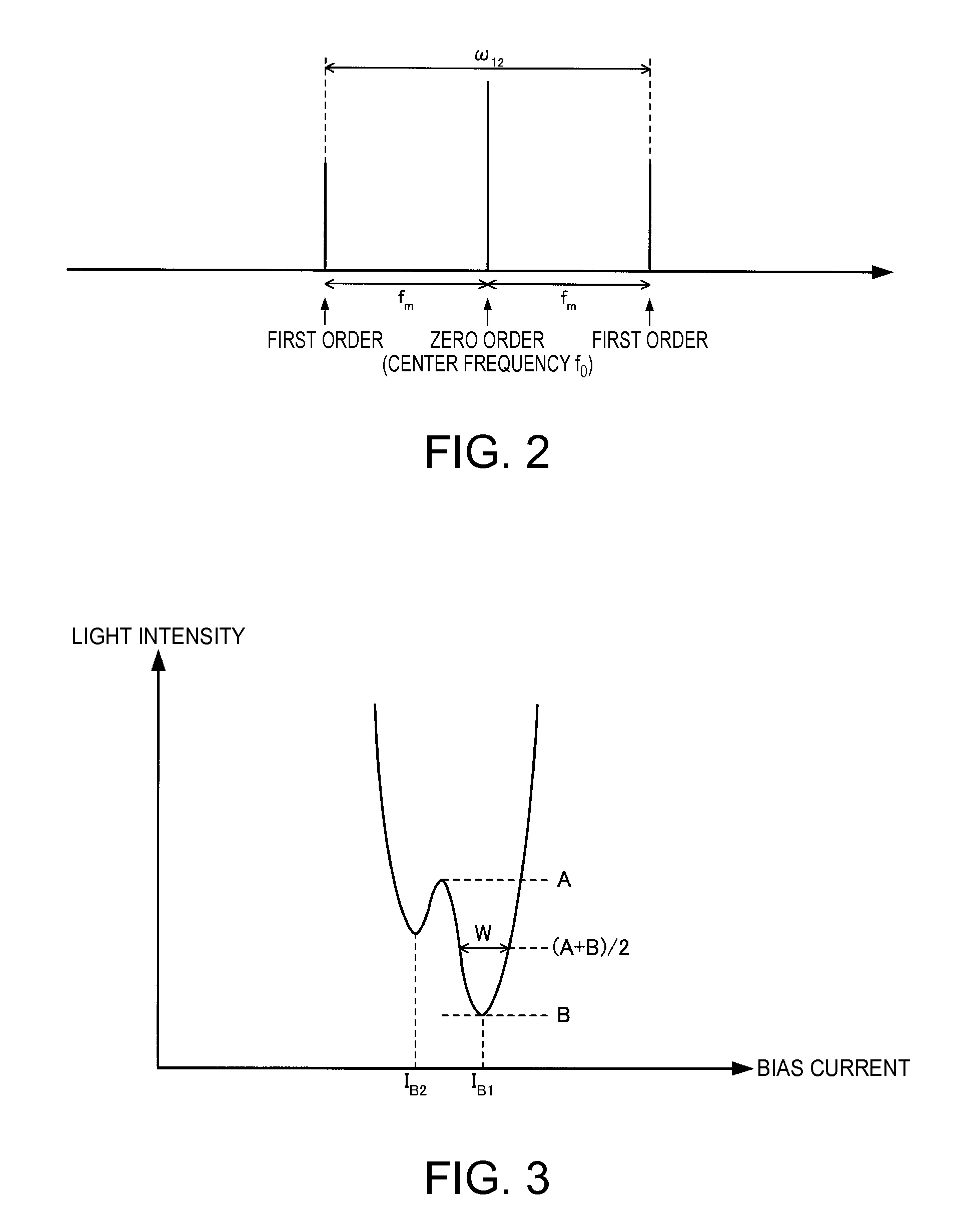
[0151]According to the atomic oscillator of the aforementioned embodiments, Zeeman Splitting occurs in the energy levels of the alkali metal atoms if a magnetic field is applied to the gas cell 13, and the frequency difference ω12 of the resonance light pair which causes the EIT phenomenon varies depending on intensity of the magnetic field (the oscillation frequency varies as a result). By utilizing this property, it is possible to apply the atomic oscillator according to the embodiments to a magnetic sensor.

[0152]In addition, since the atomic oscillator according to the embodiments can create a significantly stable quantum interference state (quantum coherence state) of the alkali metal atoms, it is possible to realize a light source used for quantum information devices such as a quantum computer, a quantum memory, and a quantum cryptographic system by extracting the resonance light pair which is incident on the gas cell 13.

[0153]The invention is not limited...


PUM


Abstract

An atomic oscillator includes a gas cell, a semiconductor laser, a light detector, a bias current control section controlling a bias current based on intensity of light detected by the light detector, a memory, and an MPU. The MPU sweeps the bias current and stores a value of the bias current and a value of the intensity of the light when the intensity of the detected light shifts from a decrease to an increase and re-sweeps to set the bias current based on the value of the bias current stored in the memory after the sweep, compares the value of the intensity of the detected light with the value of the intensity of the light stored in the memory while the bias current control section controls the bias current, and determines whether to perform the sweep again in accordance with the comparison.

Description

BACKGROUND[0001]1. Technical Field[0002]The present invention relates to an atomic oscillator, an electronic apparatus, and a moving object.[0003]2. Related Art[0004]As shown in FIG. 13, a cesium atom, which is a kind of alkali metal atom, has a ground level of 6S1 / 2 and two excitation levels of 6P1 / 2 and 6P3 / 2, and furthermore, the respective levels of 6S1 / 2, 6P1 / 2, and 6P3 / 2 have ultrafine structures with a plurality of split energy levels. Specifically, 6S1 / 2 has two ground levels F=3 and 4, 6P1 / 2 has two excitation levels F′=3 and 4, and 6P3 / 2 has four excitation levels F′=2, 3, 4, and 5.[0005]For example, a cesium atom in a ground level F of 6S1 / 2=3 can shift to one of the excitation levels F′ of 6P3 / 2=2, 3, and 4, by absorbing a D2 beam while the cesium atom cannot shift to the excitation level F′=5. A cesium atom in the ground level F of 6S1 / 2=4 can shift to one of the excitation levels F′ of 6P3 / 2=3, 4, and 5 by absorbing the D2 beam while the cesium atom cannot shift to the...

Claims


Application Information

Patent Timeline
Patent Type & Authority Patents(United States)
IPC IPC(8): H03L7/26G04F5/14H03L1/00H03L5/00
CPCH03L7/26G04F5/145H03L1/00H03L5/00
Inventor TANAKA, NORIAKICHINDO, KOJIYOSHIDA, HIROYUKIMAKI, YOSHIYUKI
Owner SEIKO EPSON CORP
Why Eureka
Try Eureka