Resin film formation method and resin film formation device

A resin film and substrate technology, which is applied in the manufacture of optical record carriers and optical record carriers, can solve the problems of difficult irradiation of radiation, difficult resin film thickness, large-scale devices, etc., and achieve the effect of improving irradiation efficiency and clear boundaries

Inactive Publication Date: 2009-08-19
ORIGIN ELECTRIC CO LTD
View PDF3 Cites 3 Cited by
  • Summary
  • Abstract
  • Description
  • Claims
  • Application Information

AI Technical Summary

Problems solved by technology

However, if this method is used, when the radiation curable resin is irradiated with radiation while the radiation curable resin is spread by the spin coating method, the radiation curable resin that is thrown off will adhere to the mask member and be cured. , therefore, it is difficult to irradiate the radiation during the extension process
Furthermore, in the radiation irradiation methods disclosed in Patent Documents 4 and 5, when the radiation is irradiated with a rotating device, the radiation-curable resin that is thrown off will adhere to the inner wall of the rotating device and be cured. Therefore, there is a problem that the radiation irradiation process must be performed at a position different from that of the rotating device.
In addition, since the method of shielding the mask member from light cannot make the mask member come into contact with the radiation curable resin, the leaked radiation will irradiate the resin film, so that the softened and cured boundary region of the resin film is halfway. Therefore, even if the high-speed rotation process is performed thereafter, it is difficult to make the thickness of the resin film uniform
In addition, since the mask mechanism is provided, there is a problem of not only increasing the size and complexity of the device, but also increasing the cost.

Method used


Image

  • Resin film formation method and resin film formation device
  • Resin film formation method and resin film formation device
  • Resin film formation method and resin film formation device

Examples


Embodiment approach 1

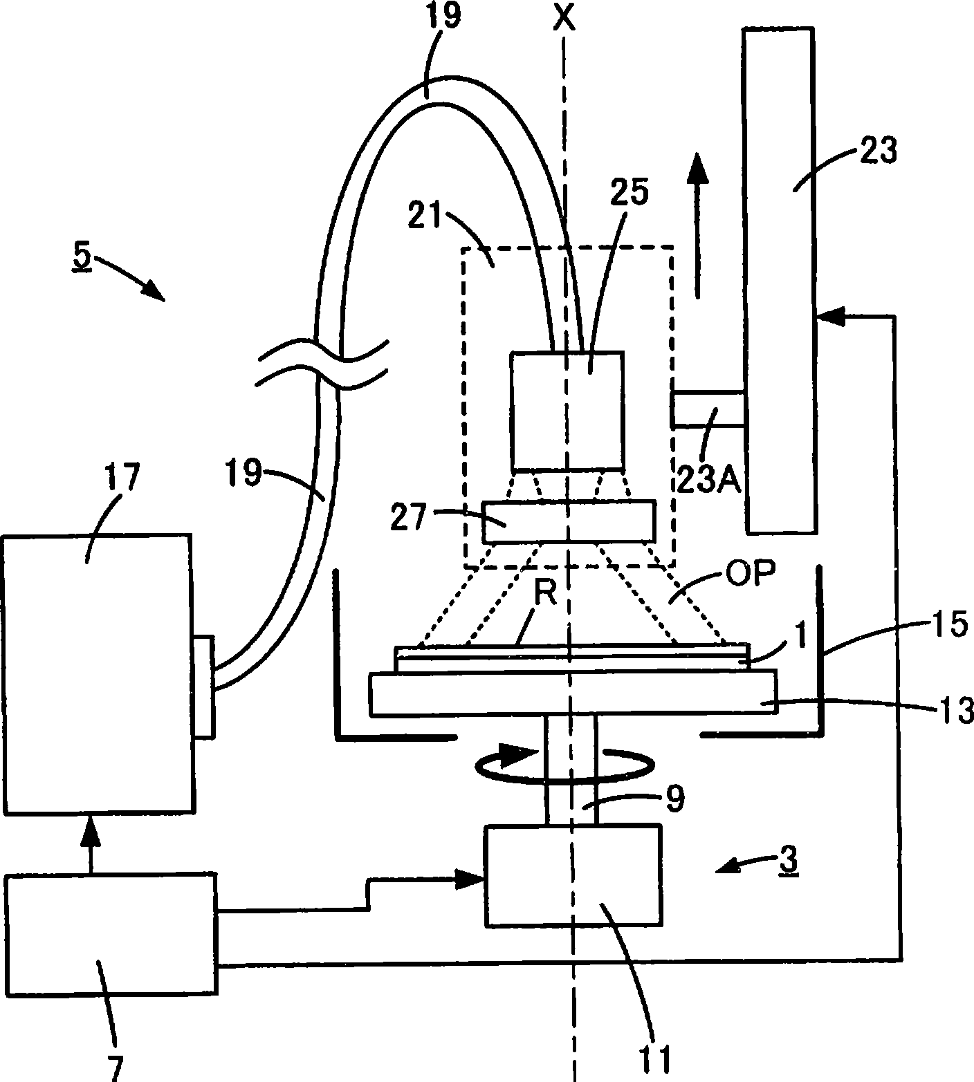
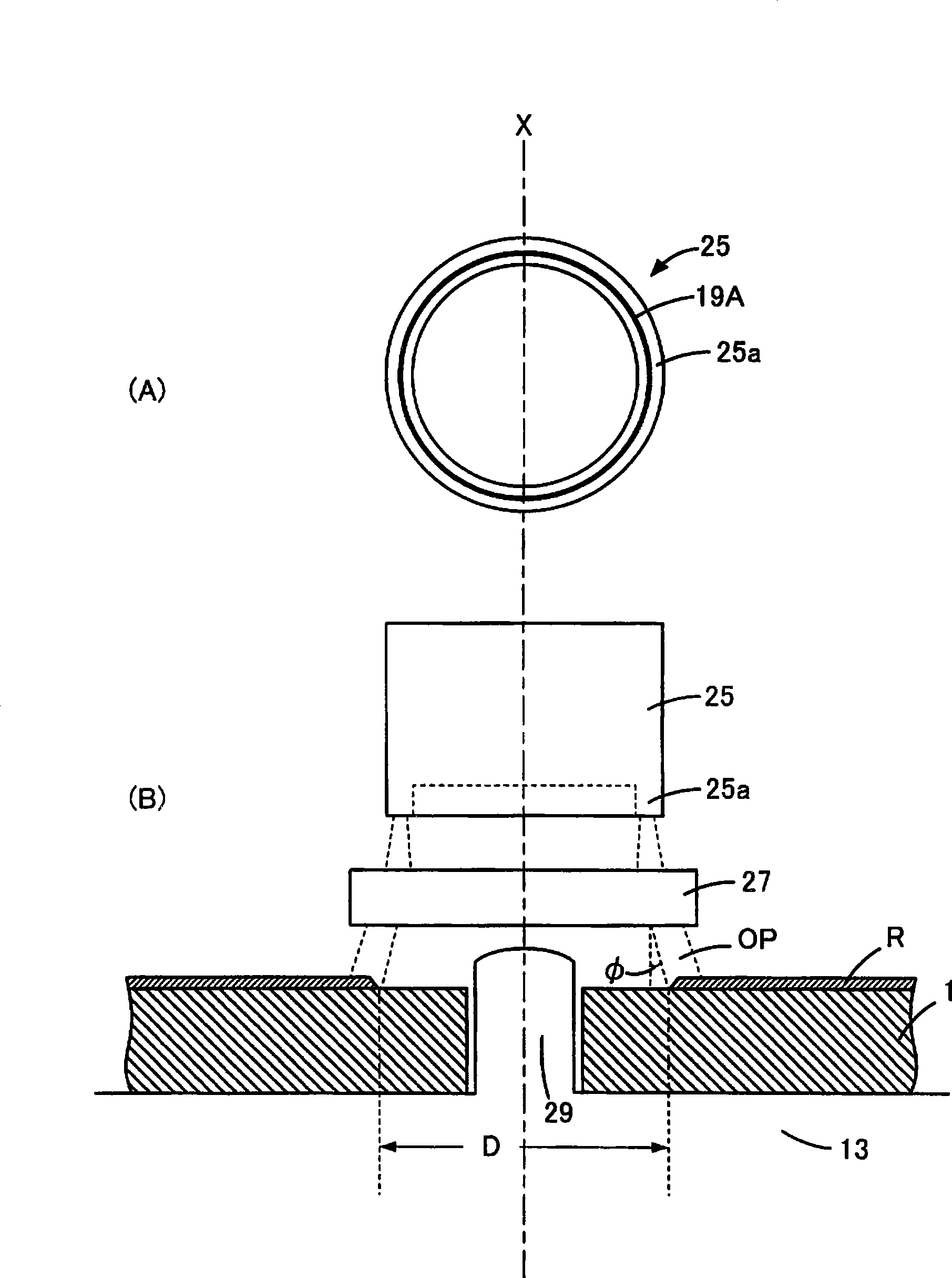
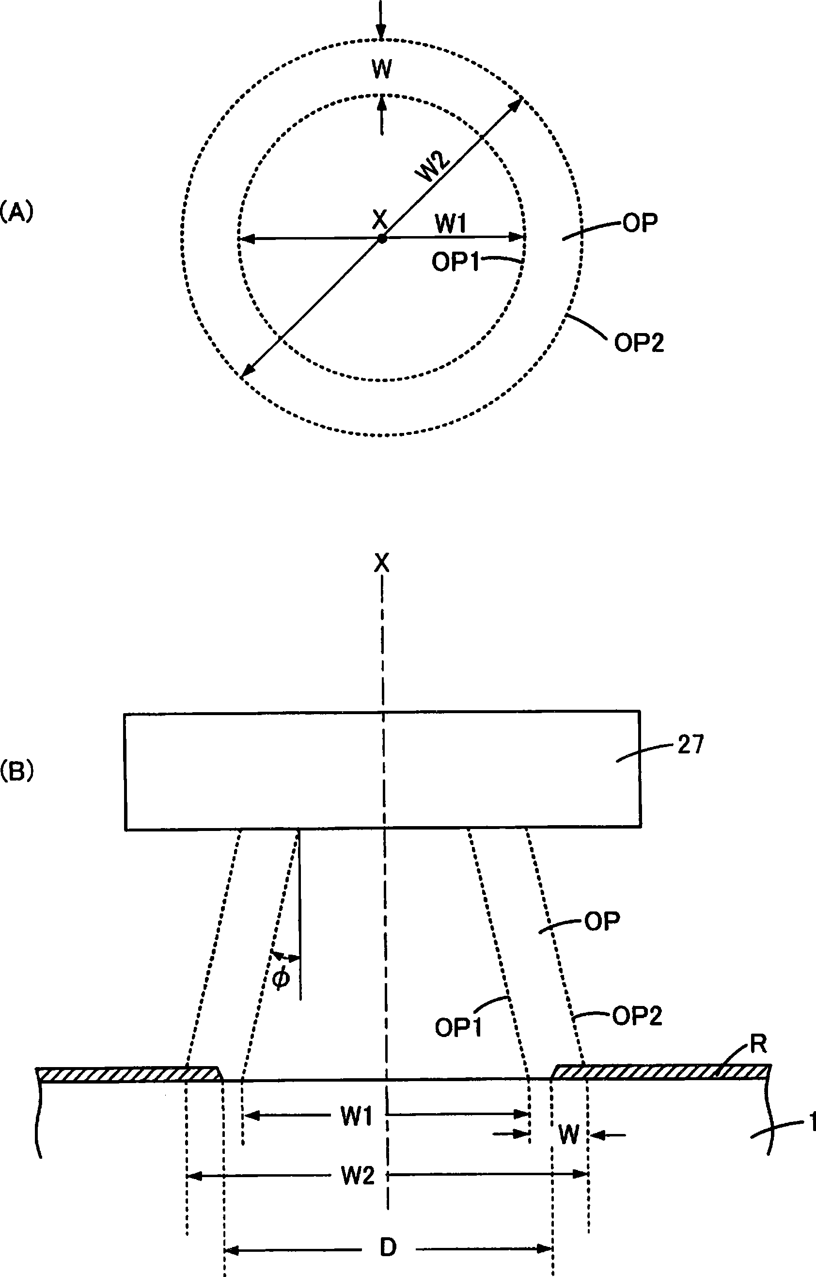
[0048] pass Figure 1 to Figure 4 The resin film forming method and resin film forming apparatus according to Embodiment 1 of the present invention will be described. figure 1 It is a figure for explaining the resin film forming apparatus of Embodiment 1 of this invention, figure 2 It is a figure which shows the lower surface of the light irradiation part. image 3 It is a figure for explaining the circular light irradiated on the board|substrate, Figure 4 It is a figure which shows an example of the rotation pattern of a board|substrate, and the raising speed pattern of an optical irradiation head. First, through figure 1 The outline of this resin film forming apparatus will be described. The resin film forming apparatus includes: a substrate rotation mechanism 3 for rotating a substrate 1 such as a second-generation large-capacity optical disc around a rotation center X according to a selected rotation pattern; A light irradiation mechanism 5 for irradiating annular ul...

Embodiment approach 2

[0062] according to Figure 5 and Figure 6 Embodiment 2 of the present invention will be described. Figure 5 It is a figure which shows an example of the light irradiation mechanism used for the resin film forming apparatus of Embodiment 2, Figure 6 It is a figure which shows the partial cross section of 25 A of ring-shaped light irradiation parts of 5 A of light irradiation mechanisms. exist Figure 5 and Figure 6 in, with in Figure 1 to Figure 4 The reference numerals used in the same reference numerals denote the components of the same name. The light irradiation head 21A shown by the dotted line is composed of the front end portion of the optical cable 19 bundled with a plurality of optical fibers and the annular light irradiation part 25A. The annular light irradiation part 25A is composed of the first annular light forming part 31 and the second annular light The light forming part 33 is constituted, and the above-mentioned first ring-shaped light forming part...

Embodiment approach 3

[0067] according to Figure 7 A resin film forming apparatus according to Embodiment 3 of the present invention will be described. exist Figure 7 in, with in Figure 1 to Figure 6 The reference numerals used in the same reference numerals denote the components of the same name. Embodiment 3 is characterized in that the photoirradiation head 21B indicated by the dotted line on the photoirradiation mechanism 5B, in particular, the annular light OP output from the photoirradiation head 21B is irradiated on the substrate 1 after being intersected. By enlarging the head 21B, ring-shaped light OP with higher light intensity can be obtained. This light irradiation head 21B is made up of the following parts: the front end part of optical cable 19; The lens member 27 that is disposed opposite to the front end surface vicinity of optical cable 19; The first reflection member 35; Member 37. The lens member 27 is, for example, a lens member called a collimator lens, which makes the ...


PUM

PropertyMeasurementUnit
thicknessaaaaaaaaaa
absorption wavelengthaaaaaaaaaa

Abstract

To form a resin film having a uniform thickness and excellent smoothness, to provide a substrate which does not warp and has excellent planarity, and to clarify whether the resin film at the boundary between light irradiation region and light non-irradiation region is hardened or not. At the time of or after flatting a liquid substance applied on a substrate by rotation, light irradiation is shifted from the center of the substrate toward the outer circumference and the liquid substance is hardened to form a resin film. The light is annularly applied, and the inner diameter and the outer diameter of the annular light concentrically increase with the rotation center axis line with the lapse of the irradiation time, and the annular light shifts from the inner circumference toward the outer circumference on the substrate.

Description

technical field [0001] The present invention relates to a resin film forming method and a resin film forming apparatus suitable for forming an adhesive layer with a uniform film thickness between a substrate such as an optical disk and a substrate, or forming a resin film with a uniform film thickness on the substrate. Background technique [0002] In general, optical discs (second-generation optical discs) basically have the following structure: For example, a structure in which one or two recording layers are formed on a transparent resin substrate with a thickness of about 1.1 mm and protected with a transparent resin film ; Or use a transparent adhesive resin film to bond two transparent resin substrates with a thickness of about 0.6mm. In this case, the signal recording layer may be formed on only one of the above-mentioned transparent resin substrates, or the signal recording layer may be formed on two substrates, and the thickness of the two substrates may be equal, o...

Claims


Application Information

Patent Timeline
Patent Type & Authority Applications(China)
IPC IPC(8): G11B7/26
Inventor 小泽直人铃木隆之
Owner ORIGIN ELECTRIC CO LTD
Why Eureka
Try Eureka