Optical axis shift correcting device and method, and computer program

a technology of optical axis and correcting device, applied in the direction of digital signal error detection/correction, instruments, recording signal processing, etc., can solve the problems of distortion or expansion and contraction of each optical part, information needs to be already recorded, and the optical axis is easily influenced, so as to selectively correct the shift of the optical axis and achieve simple control

Inactive Publication Date: 2011-07-19
PIONEER CORP
View PDF7 Cites 2 Cited by
  • Summary
  • Abstract
  • Description
  • Claims
  • Application Information

AI Technical Summary

Benefits of technology

[0013]Consequently, it is possible to selectively correct the shift of the optical axis of the light on the surface of the light receiving element with respect to the radial direction of the optical disc, by the relatively simple control of obtaining the jitter amount of the signal obtained on the basis of the received light. For example, if the such correction is performed accordingly when the jitter amount is greater than or equal to the predetermined threshold value, regularly or irregularly in the middle of the reproduction or the recording, it is possible to continue the reproduction and the recording in the state that there is no shift in the optical axis in the radial direction of the optical axis. Incidentally, it is more effective if such correction is performed not only when the jitter amount is greater than or equal to the predetermined threshold value but also when there is a change in an environment, such as a temperature, to the extent that the state of the optical system changes.
[0062]As explained above, according to the first optical axis shift correcting apparatus of the present invention, it is provided with: the jitter amount obtaining device; the optical axis changing device; and the controlling device. According to the second optical axis shift correcting apparatus of the present invention, it is provided with: the recording feature obtaining device; the optical axis changing device; and the controlling device. According to the optical axis shift correcting method of the present invention, it is provided with: the jitter amount obtaining process; the optical axis changing process; and the controlling process. Thus, it is possible to selectively correct the shift of the optical axis of the light on the surface of the light receiving element with respect to the radial direction of the optical disc, without a need to use the information that has been already recorded on the optical disc and by the relatively simple control. Moreover, according to the computer program of the present invention, it makes a computer function as the jitter amount obtaining device, the optical axis changing device, and the controlling device. Thus, it is possible to establish the aforementioned optical axis shift correcting apparatus of the present invention, relatively easily.

Problems solved by technology

However, for example, according to the technology disclosed in the aforementioned patent document 1, since an offset is adjusted by using the information signal, there is such a technical problem that information needs to be already recorded on a recording type disc.
Moreover, even after the optical axis is once adjusted, the optical axis is easily influenced by a temperature change, which is also a problem.
Moreover, even if the adhesive is not used or in a position in which the adhesive is not used, the temperature change causes a change in a positional relationship between the optical parts to a greater or lesser degree, or it causes distortion or expansion and contraction in each optical part.
Thus, the influence of the temperature change cannot be ignored in some cases.

Method used


Image

  • Optical axis shift correcting device and method, and computer program
  • Optical axis shift correcting device and method, and computer program
  • Optical axis shift correcting device and method, and computer program

Examples


first embodiment

(1) First Embodiment

[0094]An optical axis shift correcting apparatus in a first embodiment will be explained with reference to FIG. 1 to FIG. 5. In the first embodiment, it is judged whether or not an optical axis shift is corrected focusing on a jitter amount of a reproduction signal.

[0095](1-1) Structure

[0096]Firstly, the structure of the optical axis shift correcting apparatus in the first embodiment will be explained with reference to FIG. 1 to FIG. 4.

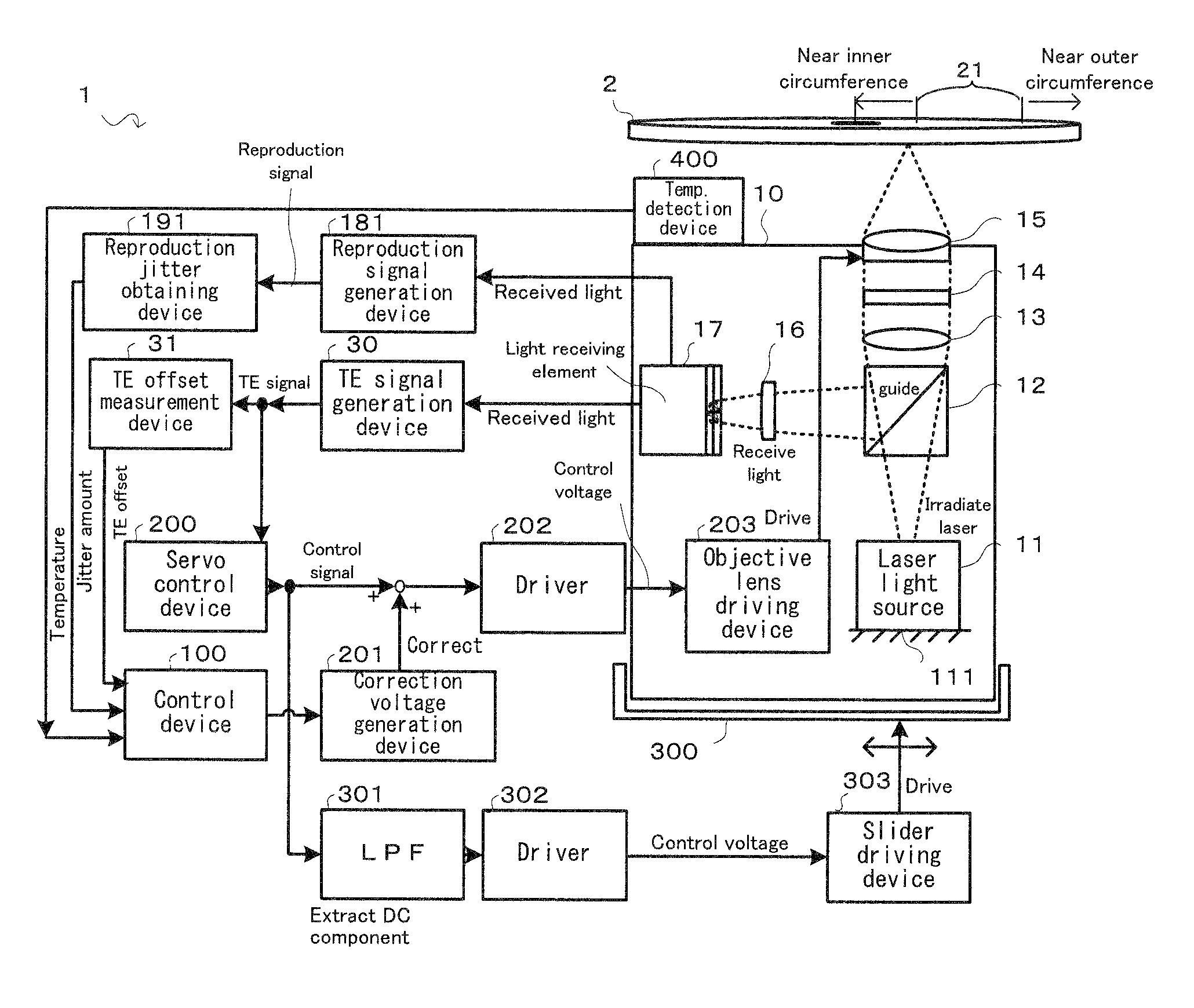
[0097]Firstly, with reference to FIG. 1, a description will be given on the basic structure of an optical information apparatus 1 provided with the optical axis shift correcting apparatus in the first embodiment. FIG. 1 is a block diagram conceptually showing the basic structure of the optical information apparatus provided with the optical axis shift correcting apparatus in the first embodiment of the present invention.

[0098]As shown in FIG. 1, the optical information apparatus 1 provided with the optical axis shift correcting app...

second embodiment

(2) Second Embodiment

[0145]An optical axis shift correcting apparatus in a second embodiment will be explained with reference to FIG. 6 and FIG. 7 in addition to FIG. 1 to FIG. 5. In the second embodiment, it is judged whether or not an optical axis shift is corrected focusing on a jitter amount of a recording clock.

[0146](2-1) Structure

[0147]Firstly, with reference to FIG. 6, a description will be given on the basic structure of the optical information apparatus in the second embodiment. Incidentally, in FIG. 6, the same structure as that in FIG. 1 carries the same numerical reference, and the detailed explanation thereof will be omitted.

[0148]In the structure in FIG. 6 in the embodiment, the point that is different from the structure in FIG. 1 in the first embodiment is that it is provided with a recording clock generation device 182 in addition to or instead of the reproduction signal generation device 181 in FIG. 1 and that it is further provided with a recording jitter obtainin...

third embodiment

(3) Third Embodiment

[0158]An optical axis shift correcting apparatus in a third embodiment will be explained with reference to FIG. 8 in addition to FIG. 1 to FIG. 7. In the third embodiment, the optical axis shift is corrected without stopping the recording, focusing on the jitter amount of the recording clock.

[0159](3-1) Structure

[0160]The basic structure of the optical information apparatus provided with the optical axis shift correcting apparatus in the embodiment may be the same as that in the second embodiment. The explanation will be omitted to avoid redundancy. That is, the basic structure in the embodiment is as shown in FIG. 6.

[0161](3-2) Operation

[0162]Next, the operation of the optical axis shift correcting apparatus in the embodiment will be explained by using FIG. 8. Incidentally, in FIG. 8, the same step as that in FIG. 5 and FIG. 7 carries the same numerical reference, and the detailed explanation thereof will be omitted, as occasion demands. In the processes in FIG....


PUM

PropertyMeasurementUnit
temperatureaaaaaaaaaa

Abstract

An optical axis shift correcting device is provided in an optical information device including an irradiation element for applying a laser, an optical system for guiding a laser applied to an optical disc having a recording track, and a light reception element for receiving the light from the optical disc generated by the guided laser via the optical system. The optical axis shift correcting device includes a jitter acquisition element, an optical axis modification element modifying the direction of the optical axis with respect to the light reception element, and a control element controlling the optical axis modification element to reduce the shift when the acquired jitter amount exceeds a predetermined threshold value. The optical axis shift correcting device thus corrects the optical axis light shift on the surface of the light reception element with respect to the radial direction of the optical disc set in the optical information device.

Description

TECHNICAL FIELD[0001]The present invention relates to an optical axis shift correcting apparatus and method, which is provided for an optical information apparatus, such as a DVD recorder, and which corrects a shift or misalignment in the optical axis of a laser beam in the radial direction of an optical disc, and a computer program which makes a computer function as such an optical axis shift correcting apparatus.BACKGROUND ART[0002]Under the current environment that a conventional optical disc (e.g. a CD (Compact Disc), a DVD) and a next-generation optical disc (e.g. a Blu-ray Disc: BD) are mixed, it is required to provide compatibility for recording and reproduction of each optical disc. However, in order to realize an optical pickup apparatus that has the compatibility, an optical axis shift can be an issue.[0003]In order to deal with such a trouble, for example, an optical axis correction technology has been suggested (refer to a patent document 1). According to this technology...

Claims


Application Information

Patent Timeline
Patent Type & Authority Patents(United States)
IPC IPC(8): G11B7/00
CPCG11B7/094G11B7/0956G11B2007/0006
Inventor SASAKI, YOSHIOOONO, KENICHIOSHIMA, YASUSHI
Owner PIONEER CORP
Why Eureka
Try Eureka