Diagnostic equipment for an exhaust gas cleaning apparatus

a technology of diagnostic equipment and exhaust gas, which is applied in mechanical equipment, machines/engines, electric control, etc., can solve the problems of inability to decide the inability to determine the deterioration state of the catalyst or air-fuel-ratio sensor, so as to prevent air pollution and eliminate wasteful expenses

Inactive Publication Date: 2006-10-10
HITACHI LTD
View PDF31 Cites 10 Cited by
  • Summary
  • Abstract
  • Description
  • Claims
  • Application Information

AI Technical Summary

Benefits of technology

[0008]An object of the present invention is to provide a diagnostic equipment for an exhaust gas cleaning apparatus, in which the accuracy of the detection of the deterioration of an air-fuel-ratio sensor as well as a catalyst is prevented from lowering even when the misfire of an engine and the failure of a secondary air system have taken place.
[0022]As stated above, according to the corresponding one of the aspects of performance of the present invention, the degree of deterioration of the catalyst or the air-fuel-ratio sensor is not erroneously decided even when the misfire of the engine and the failure or deterioration of the secondary air system has occurred. It is therefore avoided to replace the catalyst or the air-fuel-ratio sensor in spite of no deterioration thereof, or to run the engine in spite of the deterioration of the catalyst or the air-fuel-ratio sensor without the replacement thereof. Accordingly, the present invention serves to eliminate wasteful expenses and to prevent air pollution.

Problems solved by technology

The decision of the deterioration state of the catalyst or air-fuel-ratio sensor may well be interrupted in a case where the frequence in the misfire is high or where the failure of the secondary air system is heavy.
On this occasion, the deterioration state of the catalyst or air-fuel-ratio sensor cannot be decided.
In general, however, the misfire of the engine and the failure of the secondary air system do not often occur, and such a construction is satisfactory in many uses.

Method used


Image

  • Diagnostic equipment for an exhaust gas cleaning apparatus
  • Diagnostic equipment for an exhaust gas cleaning apparatus
  • Diagnostic equipment for an exhaust gas cleaning apparatus

Examples


second embodiment

[0083]Now, a diagnostic equipment for deciding the deterioration of an air-fuel-ratio sensor will be described as the present invention.

first embodiment

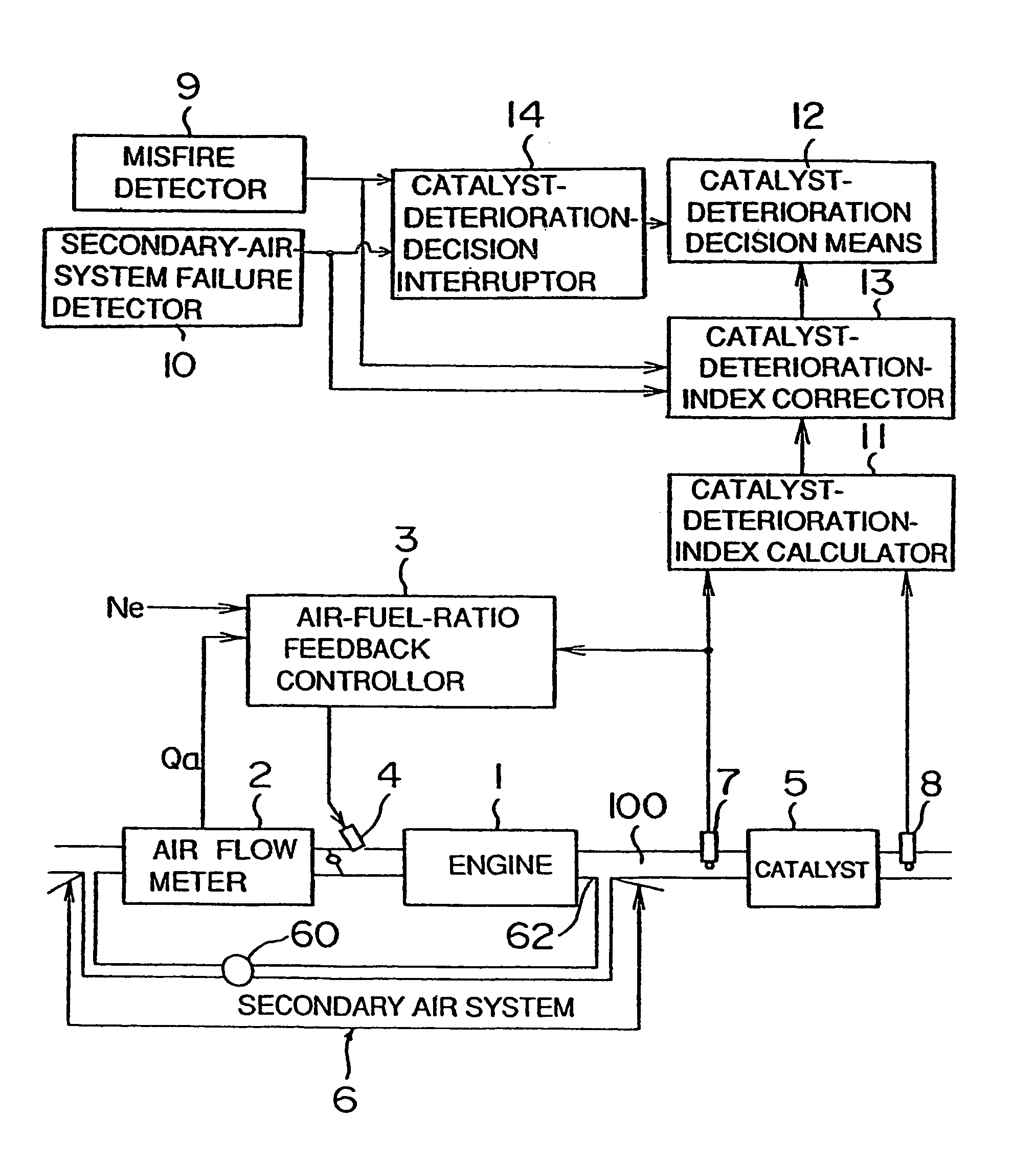
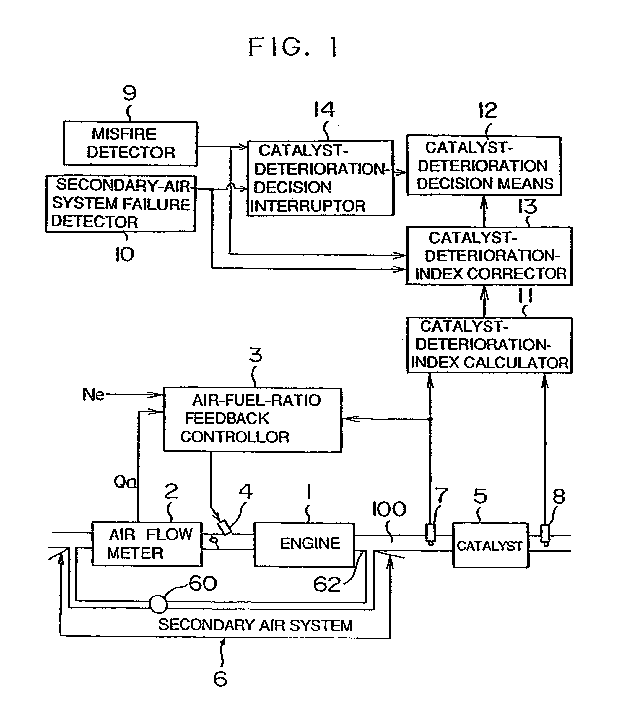
[0084]FIG. 11 generally illustrates the construction of the diagnostic equipment in this embodiment, together with that of an engine system to which the diagnostic equipment is applied. An engine 1, an air flow meter 2, air-fuel-ratio feedback control means 3, an injector 4, an air-fuel-ratio sensor 7, etc. are the same as those described in the first embodiment, respectively.

[0085]The diagnostic equipment is constructed comprising misfire detection means 9, secondary-air-system failure detection means 10, sensor-deterioration-index calculation means 21, sensor-deterioration decision means 22, sensor-deterioration-index correction means 23 and sensor-deterioration-decision interruption means 24.

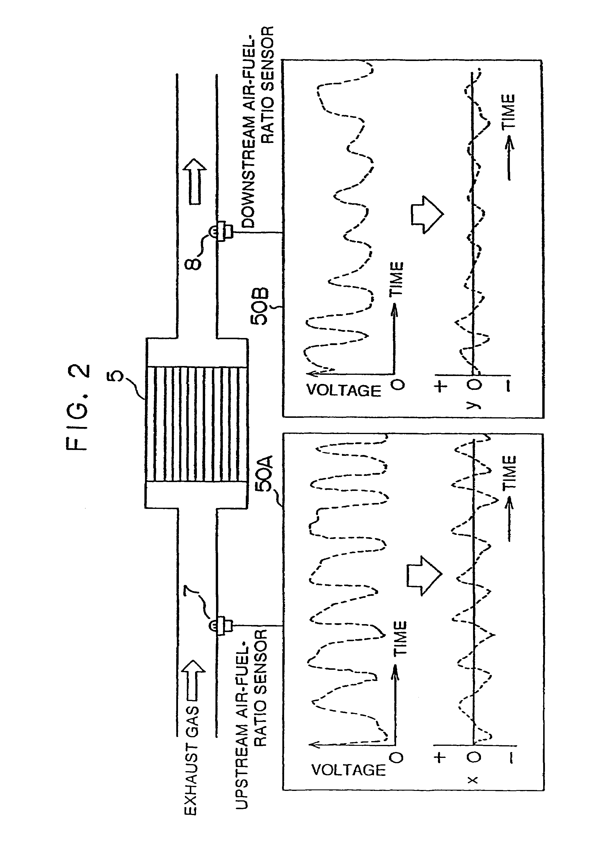
[0086]The sensor-deterioration-index calculation means 21 serves to detect the deterioration state of the air-fuel-ratio sensor 7. In this embodiment, the detection of the deterioration state is effected using the auto-correlation function of the output signal of the air-fuel-ratio sensor 7. ...


PUM


Abstract

A diagnostic equipment for an exhaust gas cleaning apparatus installed for an engine, comprising a misfire detector which detects the misfire of the engine, and a secondary-air-system failure detector which detects the failure of a secondary air system. An index corrector corrects a deterioration index calculated by a deterioration-index calculator, in accordance with the detected result of the detector. A deterioration decision unit decides if the diagnostic equipment has failed, by the use of the corrected deterioration index. In a case where the extent of the misfire or the like is severe, a decision interrupter interrupts the decision of the deterioration decision unit. Thus, even when the misfire of the engine or the failure of the secondary air system has occurred, the detection of the deterioration of a catalyst does not err. It is therefore avoided to erroneously replace the catalyst which has not deteriorated yet, or to run the engine in spite of the deterioration of the catalyst.

Description

BACKGROUND OF THE INVENTION[0001]1. Field of the Invention[0002]The present invention relates to a diagnostic equipment for an exhaust gas cleaning apparatus installed in an engine system. More particularly, it relates to a diagnostic equipment for an engine exhaust gas cleaning apparatus which employs a catalyst together with a so-called “UEGO sensor(universal exhaust gas oxygen sensor)” that serves to measure an air fuel ratio in a wide range of air-fuel-ratio values or a so-called “O2-sensor” (oxygen sensor) that generates a binary output on the basis of a sudden output change near a stoichiometric ratio (hereinbelow, both the sensors shall be collectively called an “air-fuel-ratio sensor”).[0003]2. Description of the Related Art[0004]A well-known apparatus for cleaning the exhaust gas of an engine has a catalyst and an air-fuel-ratio feedback controller. The catalyst is incorporated in an exhaust pipe part for the purpose of eliminating HC (hydrocarbons), NOx (nitrogen oxides) a...

Claims


Application Information

Patent Timeline
Patent Type & Authority Patents(United States)
IPC IPC(8): F01N3/00F01N3/20F01N3/22F01N11/00F02D35/00F02D41/14F02D41/22F02D45/00F02P17/12
CPCF01N3/22F01N11/00F01N11/007F02D35/003F02D41/1441F02D41/1498F02D41/221F01N2550/02F01N2550/14F02D2200/0402F02D2200/1015Y02T10/40Y02T10/47
Inventor TAKAKU, YUTAKAISHII, TOSHIO
Owner HITACHI LTD
Why Eureka
Try Eureka