Impact extrusion molded article, and impact extrusion molding method, and an impact extrusion molding apparatus

a technology of extrusion molding and impact molding, which is applied in the direction of forging press drives, etc., can solve the disadvantageous hampered appearance of the product b>3/b>, and achieve the effect of reducing the change quantity in the metallographic structure and suppressing the metal flow

Inactive Publication Date: 2006-10-10
FURUKAWA SKY ALUMINUM CORP
View PDF8 Cites 22 Cited by
  • Summary
  • Abstract
  • Description
  • Claims
  • Application Information

AI Technical Summary

Problems solved by technology

However, when the surface treatment for coating the surface of the product 3 is not carried out, or when an anodizing, in particular, is conducted on the product 3, the region 3a having different conditions remains, with the result that the appearance of the product 3 is disadvantageously hampered.

Method used


Image

  • Impact extrusion molded article, and impact extrusion molding method, and an impact extrusion molding apparatus
  • Impact extrusion molded article, and impact extrusion molding method, and an impact extrusion molding apparatus
  • Impact extrusion molded article, and impact extrusion molding method, and an impact extrusion molding apparatus

Examples


first embodiment

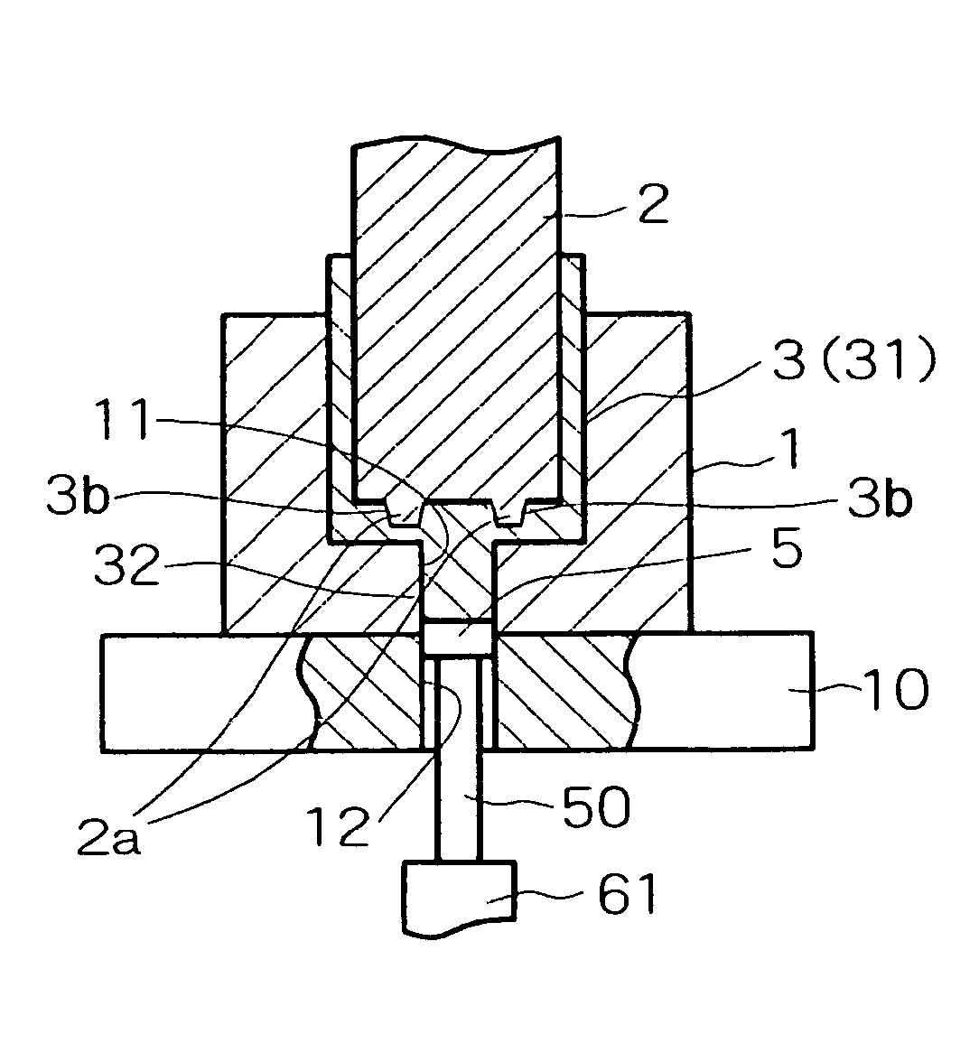
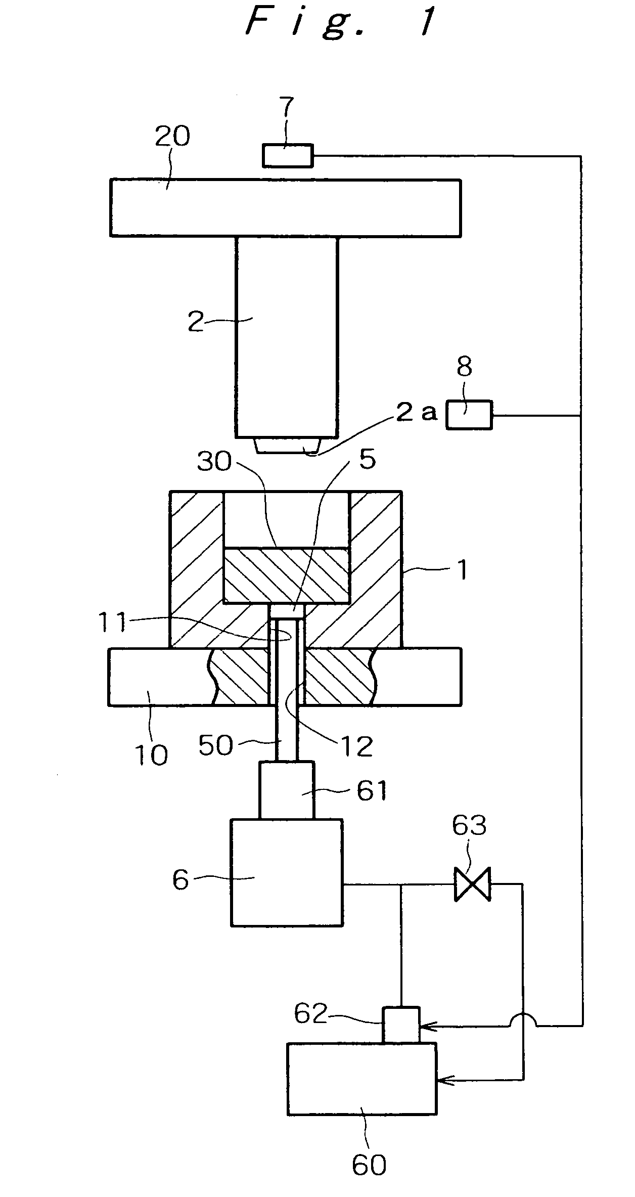
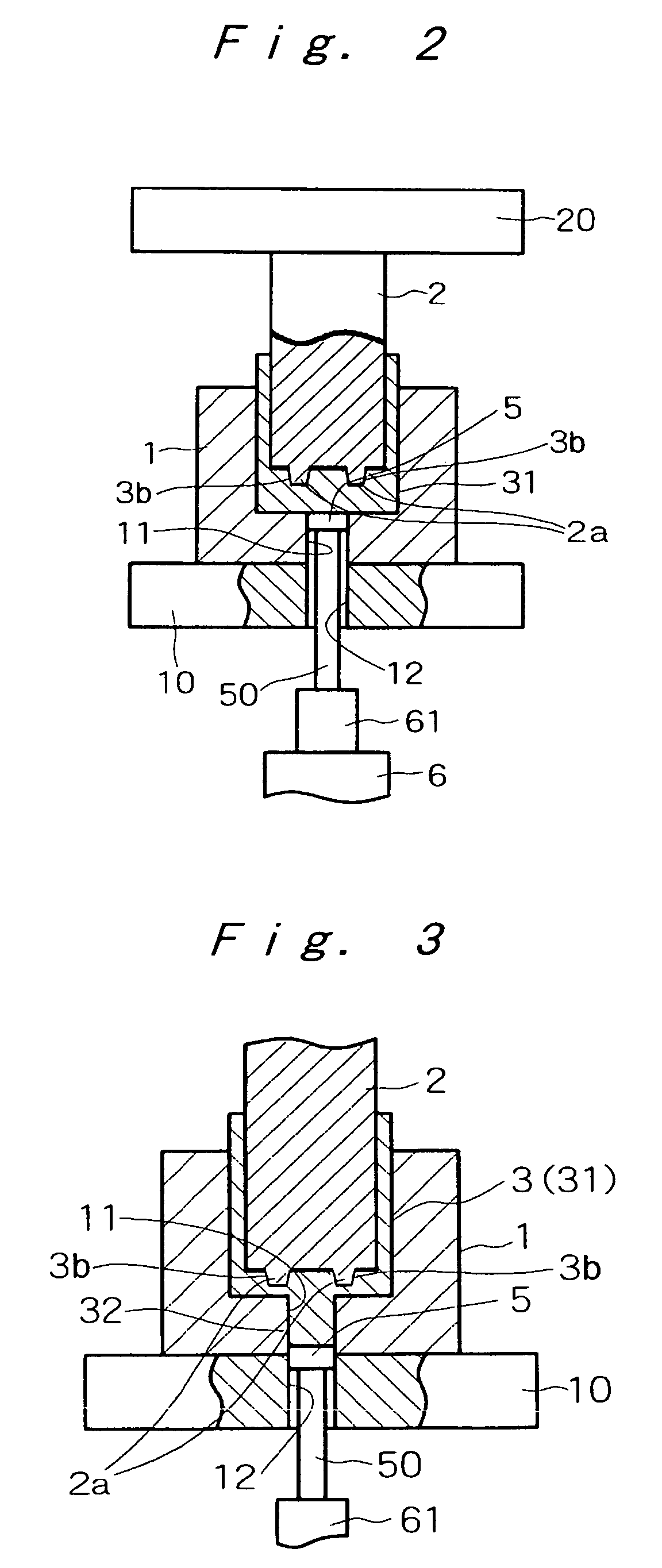
[0048]FIG. 1 is a partially sectional explanatory view showing the first embodiment of the impact extrusion molding apparatus according to the present invention. FIGS. 2 and 3 are partially sectional explanatory views showing that a semifinished product is being extrusion molded by the apparatus in the first embodiment shown in FIG. 1. FIG. 4 is an enlarged sectional explanatory view of the top end portion of a punch shown in FIG. 3. FIG. 5 is a cross-sectional view of an extrusion molded product.

[0049]In FIG. 1, a dice 1 and a punch 2 are attached to a dice holder 10 and a punch holder 20, respectively, similarly to the conventional apparatus.

[0050]Holes 11 and 12, equal in diameter and communicating with each other, are formed to go through the bottom of the dice 1, and that of the dice holder 10, respectively. A rod 50 is provided, to slide in these holes 11 and 12, and an opening / closing means 5, for opening and closing the hole 11 in the bottom of the dice 1, is provided on the...

second embodiment

[0068]FIG. 6 is a partially sectional explanatory view showing the second embodiment of the molding apparatus according to the present invention. The back pressure applying means 6 consists of a cam, having a cam shaft 64. The other constituent elements of the molding apparatus in the second embodiment, and the function and advantages thereof, are almost the same as those of the molding apparatus in the first embodiment, which will not be described herein.

third embodiment

[0069]FIG. 7 is a partially sectional explanatory view showing the third embodiment of the molding apparatus according to the present invention.

[0070]In the third embodiment, an appropriate number of cushion pins 22 are attached to the lower portion of the outer periphery of the punch holder 20. The cushion pins 22 are constituted as follows. The respective cushion pins 22 are lowered when the punch 2 is lowered; the lower end portions of the cushion pins 22 are protruded downward from guide holes 13, formed in the dice holder 10, respectively; the cushion pad 65 of the back pressure applying means 6 is pushed down, to thereby relieve the back pressure applied to the opening / closing means 5. In this embodiment, it is possible to dispense with the pressure sensor 7 and the position sensor 8, shown in FIG. 1.

[0071]The other constituent elements of the molding apparatus in this embodiment, and the function and advantages thereof, are almost the same as those of the molding apparatus in...


PUM

PropertyMeasurementUnit
thicknessaaaaaaaaaa
thicknessaaaaaaaaaa
heightaaaaaaaaaa

Abstract

An impact extrusion molded article that is molded while the metal-flow from a bottom of a slug set in a dice toward the side of the molded product article is suppressed; an impact extrusion molding method for manufacturing the impact extrusion molded article, and an impact extrusion molding apparatus used for the impact extrusion molding method, are provided.

Description

[0001]This application is a continuation of international application PCT / JP2003 / 001447 filed on Feb. 12, 2003.TECHNICAL FIELD[0002]The present invention relates to an impact extrusion molded article, for example, a cover of small-sized equipment such as a portable game machine, a cellular phone, and the like that is a cylindrical product; to an impact extrusion molding method; and to an impact extrusion molding apparatus, for molding the product.BACKGROUND ART[0003]A conventional impact extrusion molding method will be described with reference to FIGS. 15 and 16(a) to 16(c). It should be noted that the same constituent elements are denoted by the same reference numerals throughout the drawings. FIG. 15 is a partially sectional explanatory view of a conventional impact extrusion molding apparatus. FIG. 16(a) is a front view of a slug, which is a material; FIG. 16(b) is a cross-sectional view of a semifinished product (intermediate molded article); and FIG. 16(c) is a perspective vie...

Claims


Application Information

Patent Timeline
Patent Type & Authority Patents(United States)
IPC IPC(8): B21C23/20B21C35/04B21C23/18B21J9/20
CPCB21C23/186B21J9/20B21C23/18
Inventor OGURA, KEN-ICHIUENO, SEIZOHOSOKAWA, TOSHIYUKIEDA, YOSHIYA
Owner FURUKAWA SKY ALUMINUM CORP
Why Eureka
Try Eureka