
Flange sleeve and method for the production thereof

a technology of flange sleeves and sleeves, which is applied in the direction of bearings, shafts, bearing bushes, etc., can solve the problems of uneven thickness distribution over the circumference of the flange, adversely affecting the properties of the pivot joint, etc., and achieve the effect of improving the thickness tolerance of walls and without risking the shape of the flang

Inactive Publication Date: 2006-10-10
GLEITLAGER
View PDF9 Cites 6 Cited by
  • Summary
  • Abstract
  • Description
  • Claims
  • Application Information

AI Technical Summary

Benefits of technology

The invention is a method for producing a flange sleeve and a flange sleeve that are optimized in terms of flange thickness and have an annular shape. The method involves making recesses on one or both edges of a band portion in a region of a later butt joint. These recesses can be made in the same work step as cutting the band material. The recesses are designed to be filled up again by the material during the pressing process, which ensures that the flange sleeve has the desired shape without losing its annular shape. The invention also relates to a flange sleeve that includes recesses on its outer circumference in the region of the butt joint. The recesses can be symmetrically placed and have a bottom and sides that extend at an angle to the upper edge of the flange sleeve. The recesses can also have a notch on the end remote from the butt joint. The technical effects of the invention include improved wall thickness tolerance and optimized flange thickness.

Problems solved by technology

In such flange sleeves, there is always the problem that flowing of the material when the at least one flange is flanged over causing an uneven distribution of thickness over the circumference of the flange.
This adversely affects the properties of the pivot joint.

Method used


Image

  • Flange sleeve and method for the production thereof
  • Flange sleeve and method for the production thereof
  • Flange sleeve and method for the production thereof

Examples


Embodiment Construction

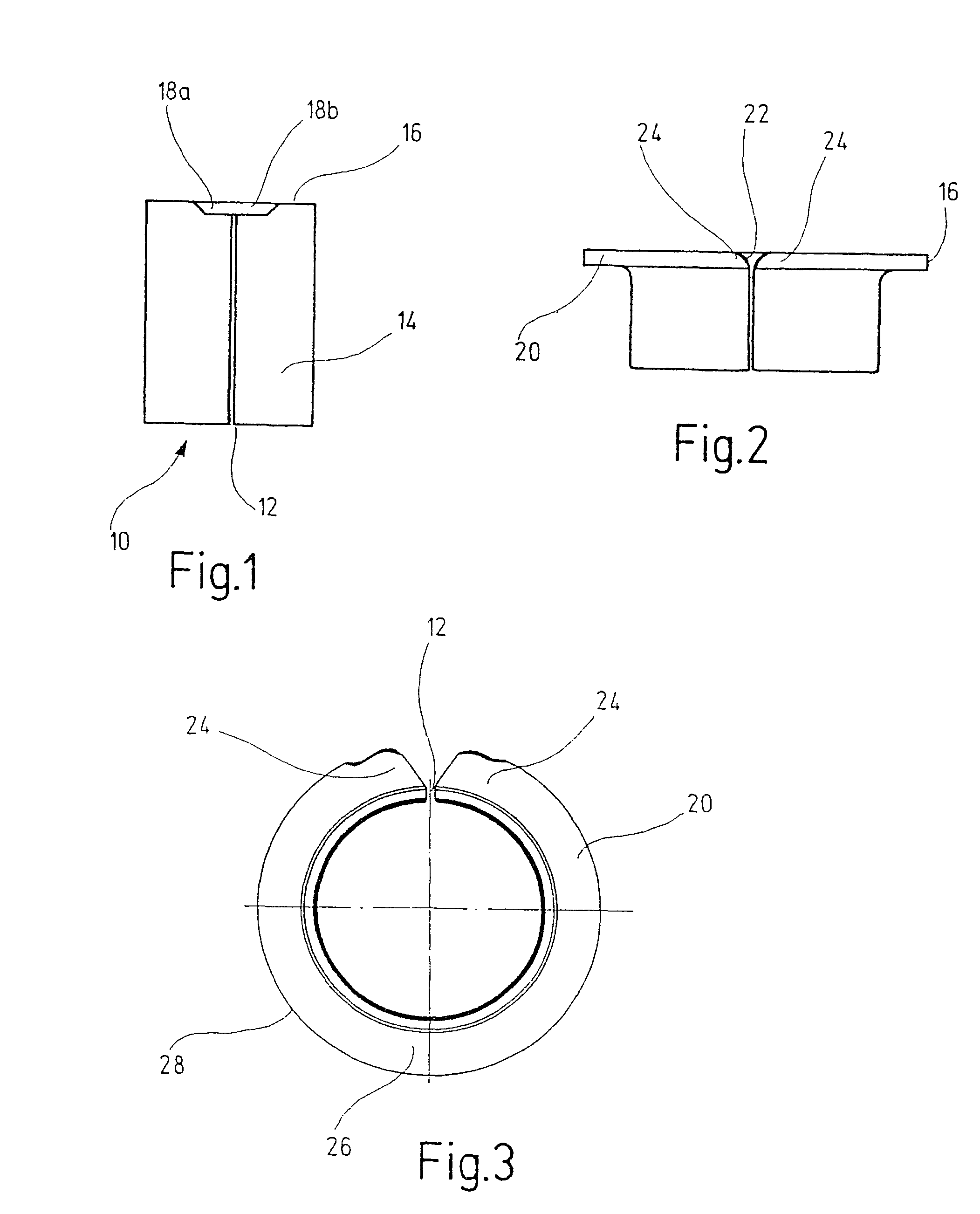
[0027]FIG. 1 shows a rolled sleeve 10; the sleeve 10 has a butt joint 12, at which the two ends of the band portion 14, having been rolled up to make the sleeve 10, abut one another.

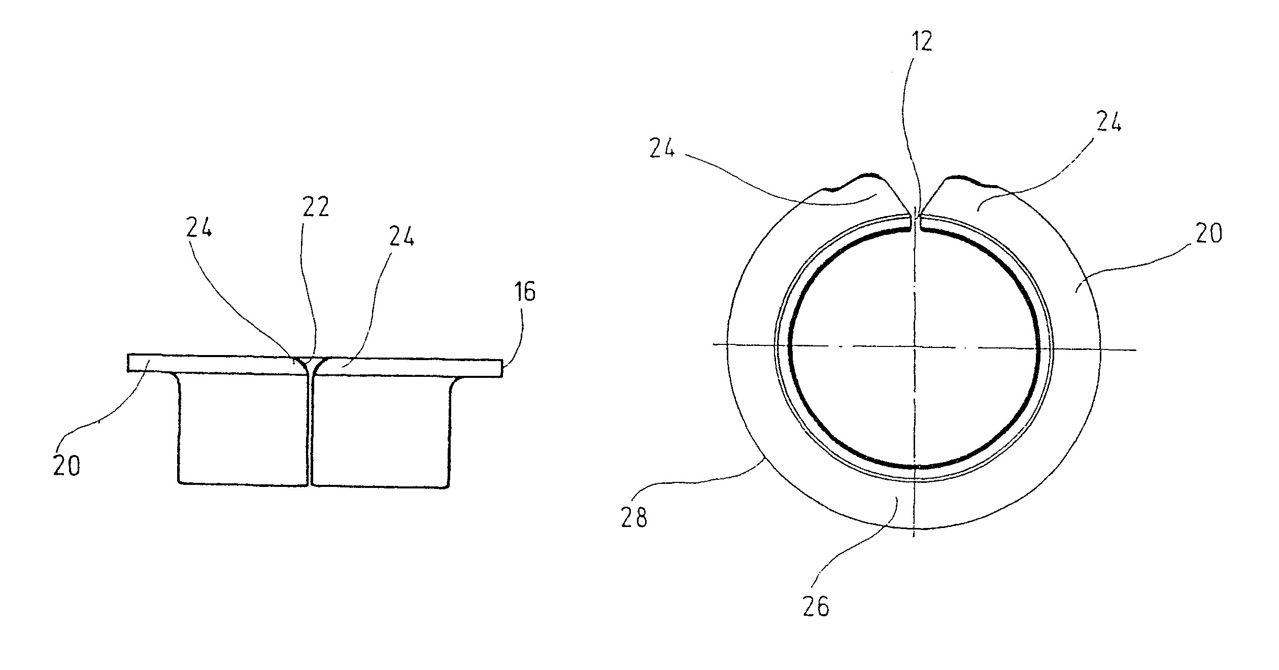
[0028]In the region of the butt joint 12, on a longitudinal edge 16 of the sleeve 10, recesses 18a and 18b are provided, which extend on into the butt joint 12 and along the circumference of the edge 16. The recesses 18a and 18b that extend in the circumferential direction are disposed symmetrically on both sides of the butt joint 12 and add up to make a single recess, before the flange is flanged over. The recesses 18a and 18b are located on the edge 16 that later forms the outer circumference of a flange 20, and they extend axially from this edge 16.

[0029]In FIG. 2, the upper edge 16 has now been flanged over to form a flange 20. The butt joint 12 has widened in the process into a V 22 in the region of the flange 20. Because of the V-shaped spreading of the flange 20 in the region of the butt joint 12 ...


PUM

PropertyMeasurementUnit
angleaaaaaaaaaa
angleaaaaaaaaaa
angleaaaaaaaaaa

Abstract

The invention relates to a method for the production of a flange sleeve (10) especially for a sliding bearing. A strip of material is cut into lengths corresponding to the later periphery of the flange sleeve. The strip section (14) thus arising is rolled to form a hollow cylindrical sleeve with an open butt joint (12) and a collar (20) is placed around one or two sides. The open butt joint is expanded in the region of the collar to form a V-shaped slit. One or several recesses (18a, 18b) are made in the region of the later open butt joint (12) on one or two of the longitudinal edges (16) of the strip section.

Description

FIELD OF THE INVENTION[0001]The invention relates to a method for producing a flange sleeve, in particular for a slide bearing, in which a band material (plate) is cut to length to suit the later circumference of the flange sleeve, and the resultant band portion is roiled up into a hollow-cylindrical sleeve with a butt joint, and after the rolling, a flange is flanged over on one or both ends, whereupon the butt joint widens in the region of the flange to form a V-shaped slit.BACKGROUND OF THE INVENTION[0002]Such flange sleeves are used, for instance, as a slide bearing for two parts contacting one another and joined by a bolt of a flat pivot joint for doors and hatches, particularly of motor vehicles.[0003]In such flange sleeves, there is always the problem that flowing of the material when the at least one flange is flanged over causing an uneven distribution of thickness over the circumference of the flange. When the material is flanged over, the flange material that is located o...

Claims


Application Information

Patent Timeline
Patent Type & Authority Patents(United States)
IPC IPC(8): B21D19/00E05D5/04E05D5/14F16C9/04F16C11/02F16C17/10F16C33/04F16C33/14F16C33/60F16C35/07
CPCF16C9/04F16C11/02F16C33/04F16C33/14F16C17/10E05D5/043E05D5/14Y10T29/49671Y10T29/49673F16C2226/30F16C2220/44F16C2220/82
Inventor GOTZMANN, MARTINBICKLE, WOLFGANGIWANSKY, JOACHIM
Owner GLEITLAGER
Learn More