Method and apparatus for controlling an elevator installation with zoning and an interchange floor

a technology of elevator installation and floor, which is applied in the direction of computer control, instruments, etc., can solve the problems of inability to open doors, and inability to solve space problems on the interchange floor, so as to reduce the round-trip time of the elevator and the travel time of passengers. , the effect of inexpensive utilization of the elevator installation

Active Publication Date: 2006-10-10
INVENTIO AG
View PDF9 Cites 16 Cited by
  • Summary
  • Abstract
  • Description
  • Claims
  • Application Information

AI Technical Summary

Benefits of technology

[0008]The purpose of the present invention is therefore to propose an elevator installation and a method of controlling the elevator installation by means of which the process of interchange from the feeder elevator to the connecting elevator is optimized and an inexpensive utilization of the elevator installation is made possible. It is especially the purpose to reduce the round-trip times of the elevators and the travel time of the passengers.

Problems solved by technology

However, as soon as a high amount of traffic to the higher range of floors with an interchange is necessary, queues may form on the interchange floor.
These are caused mainly by unequal transportation capacities between the feeder-elevator group and the connecting-elevator group but also by uncontrolled direction of interchanging passengers in the feeder elevator.
Since the available space on the interchange floors is usually limited, the space problem on the interchange floor cannot be solved without comparatively high constructional and financial outlay.
Thus, the more realistic variant is delay of the feeder elevator because an earlier arrival time of the connecting elevator by dynamically changing the acceleration and / or speed or shortening the door-opening time is either technically impossible (electrical performance, traffic density, etc.) or contra-productive for traffic optimization (skipping stops).
Furthermore, the conventional control offers no means of early recognition of the need for an interchange trip, so that no effective measures for simplification of the interchange process are possible.
However, the disadvantage of the solutions with destination-call controls hitherto is that allocation of the interchanging passengers in the first feeder elevator used takes place irrespective of the final destinations of the individual passengers and the number of final destinations.
This uncontrolled allocation requires elaborate and sometimes unclear signaling of the connecting elevators.
Also with the solutions hitherto, it is not possible to direct the passengers to the feeder elevators in such manner that the passengers of a certain feeder elevator can change to the same connecting elevator which travels to only a limited number of trip destinations.

Method used


Image

  • Method and apparatus for controlling an elevator installation with zoning and an interchange floor
  • Method and apparatus for controlling an elevator installation with zoning and an interchange floor
  • Method and apparatus for controlling an elevator installation with zoning and an interchange floor

Examples


Embodiment Construction

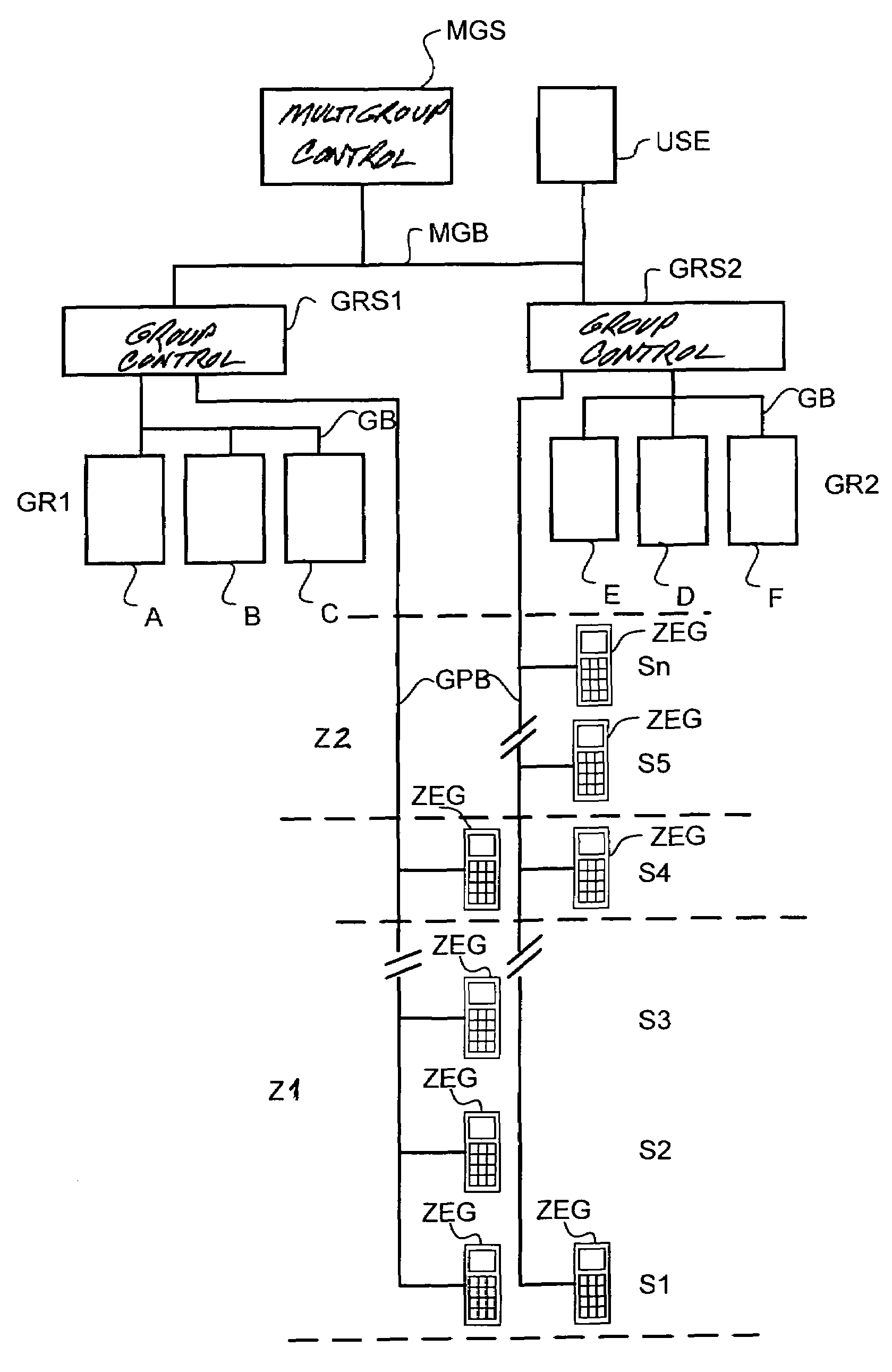
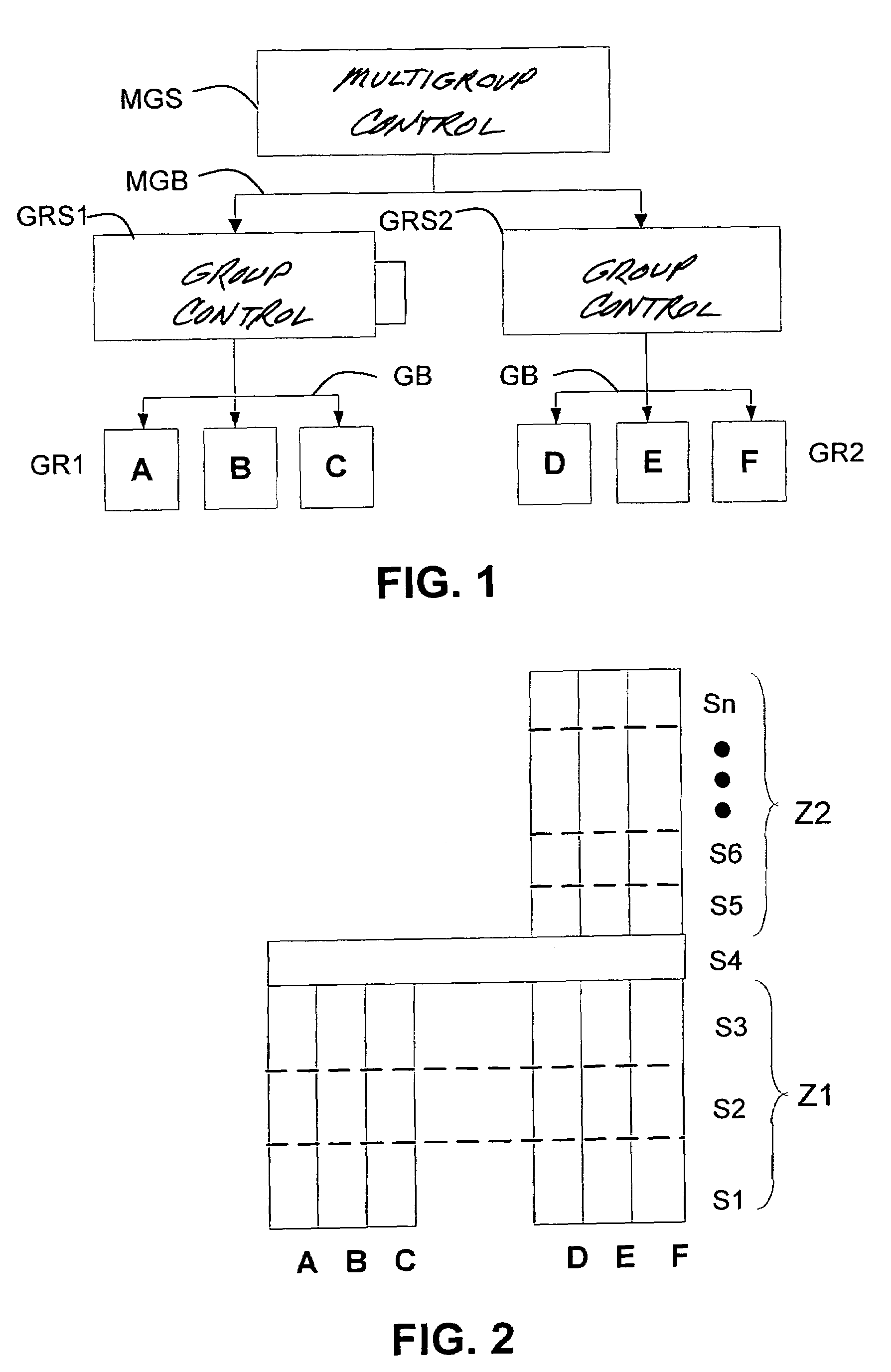
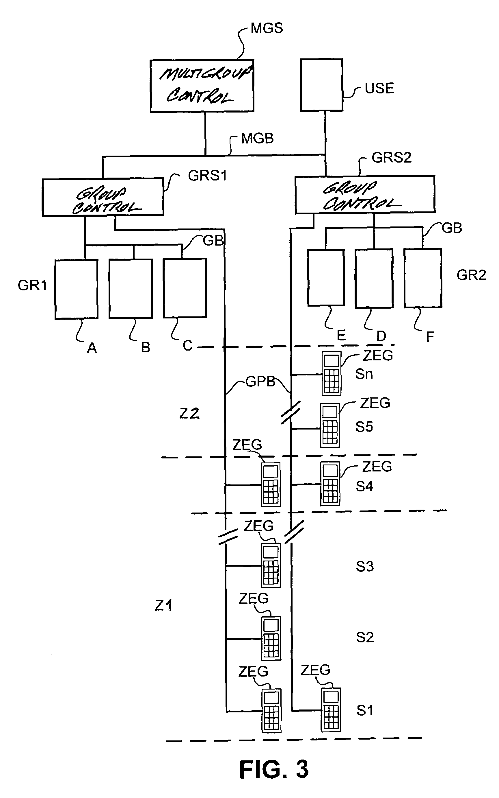
[0026]In FIG. 1 a diagrammatic structure of an elevator installation is represented in schematic form. Especially shown is the combination of two elevator groups into a multigroup with a multigroup control. The individual elevators are designated with the letters A through F, the elevators A to C being combined into a feeder-elevator group GR1 which travels to a first, or lower in a vertical direction, zone Z1 (FIG. 2) of a building. As shown in FIG. 2, floors S1 through S3 of the first zone Z1 are located below an interchange floor S4. The elevators D to F form a connecting-elevator group GR2 and travel as well as to the interchange floor S4 also to the second zone Z2 above the interchange floor S4. A superordinated multigroup control MGS is arranged centrally in a separate computer or in one or in all of group controls GRS1, GRS2. The multigroup control MGS is connected via a multigroup bus MGB with the group controls GRS1 and GRS2. The group controls GRS1 and GRS2 are connected v...


PUM


Abstract

An elevator installation control method with zoning provides changes between zones at an interchange floor. Transportation to or from the interchange floor is by at least one feeder-elevator group and at least one connecting-elevator group. The feeder-elevator group has several feeder elevators that travel in a first zone below the interchange floor and the connecting-elevator group has several connecting elevators that travel in a second zone above it. Trip destinations are entered via destination-call input and the feeder-elevator group and the connecting-elevator group are combined into a multigroup that is controlled by a multigroup control. To optimize the elevator installation operation and utilization, the multigroup control allocates a feeder elevator depending on the number of trip destinations in the first zone to be traveled to by this feeder elevator and/or on the number of trip destinations in the second zone.

Description

BACKGROUND OF THE INVENTION[0001]The present invention relates to a method for controlling an elevator installation operated with zoning in which changing between zones is made possible at an interchange floor and in which with at least one feeder-elevator group and at least one connecting-elevator group transportation to or from the interchange floor is realized. The at-least one feeder-elevator group comprises in each case several feeder elevators which travel to a first zone below an interchange floor and to the interchange floor. The at-least one connecting-elevator group comprises in each case several connecting elevators which travel to the interchange floor and to the floors of a second zone located above it. The trip destinations are input via a destination-call input. The feeder-elevator group and the connecting-elevator group are combined into a multigroup, which is controlled by a multigroup control. The present invention also relates to an elevator installation with seve...

Claims


Application Information

Patent Timeline
Patent Type & Authority Patents(United States)
IPC IPC(8): B66B1/20B66B1/18
CPCB66B1/18
Inventor WYSS, PHILIPPKOSTKA, MIROSLAY
Owner INVENTIO AG
Why Eureka
Try Eureka