Stator vane assembly for a turbomachine

a technology of turbomachine and assembly, which is applied in the direction of liquid fuel engines, vessel construction, marine propulsion, etc., can solve the problems of fan blade forced response excitation, particularly strong non-uniform pressure, and noise generation

Active Publication Date: 2006-10-10
ROLLS ROYCE PLC
View PDF12 Cites 40 Cited by
  • Summary
  • Abstract
  • Description
  • Claims
  • Application Information

AI Technical Summary

Benefits of technology

[0010]Accordingly the present invention seeks to provide a novel stator vane assembly for a turbomachine, which reduces, preferably overcomes, the above-mentioned problems.

Problems solved by technology

The pressure non-uniformity is particularly strong in the fan duct due to the pylon and struts which extend radially across the fan duct and also due to a fairing for a radial drive shaft which extends radially across the fan duct and which may be located at the bottom of the gas turbine engine.
These obstacles, the pylon, the struts and the fairing, generate circumferentially varying pressure levels, which may result in fan blade forced response excitation, noise generation and an increase in aerodynamic losses.

Method used


Image

  • Stator vane assembly for a turbomachine
  • Stator vane assembly for a turbomachine
  • Stator vane assembly for a turbomachine

Examples


Embodiment Construction

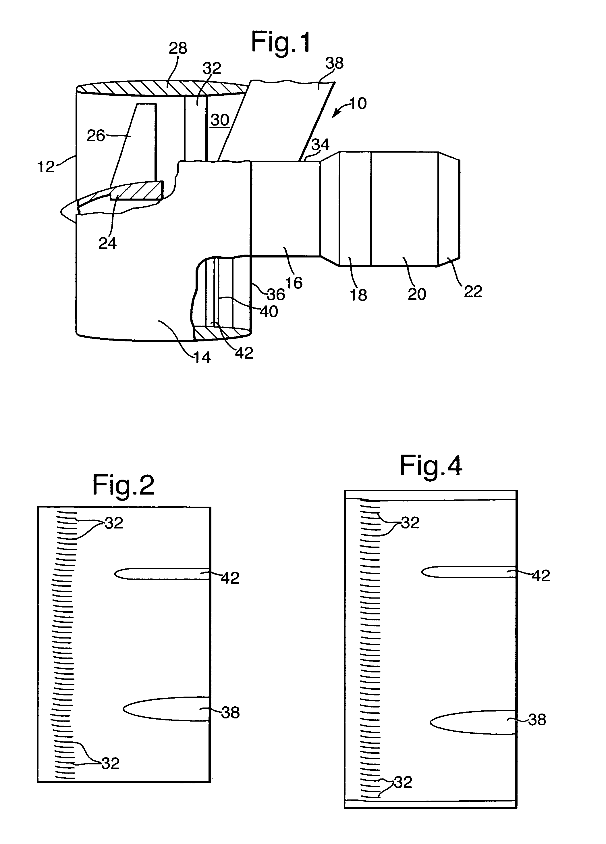
[0038]A turbofan gas turbine engine 10, as shown in FIG. 1, comprises in axial flow series an inlet 12, a fan section 14, a compressor section 16, a combustion section 18, a turbine section 20 and an exhaust 22. The turbine section 20 comprises one or more turbines (not shown) arranged to drive the fan section 14. The turbine section 20 also comprises one or more turbines (not shown) arranged to drive the compressor section 16.

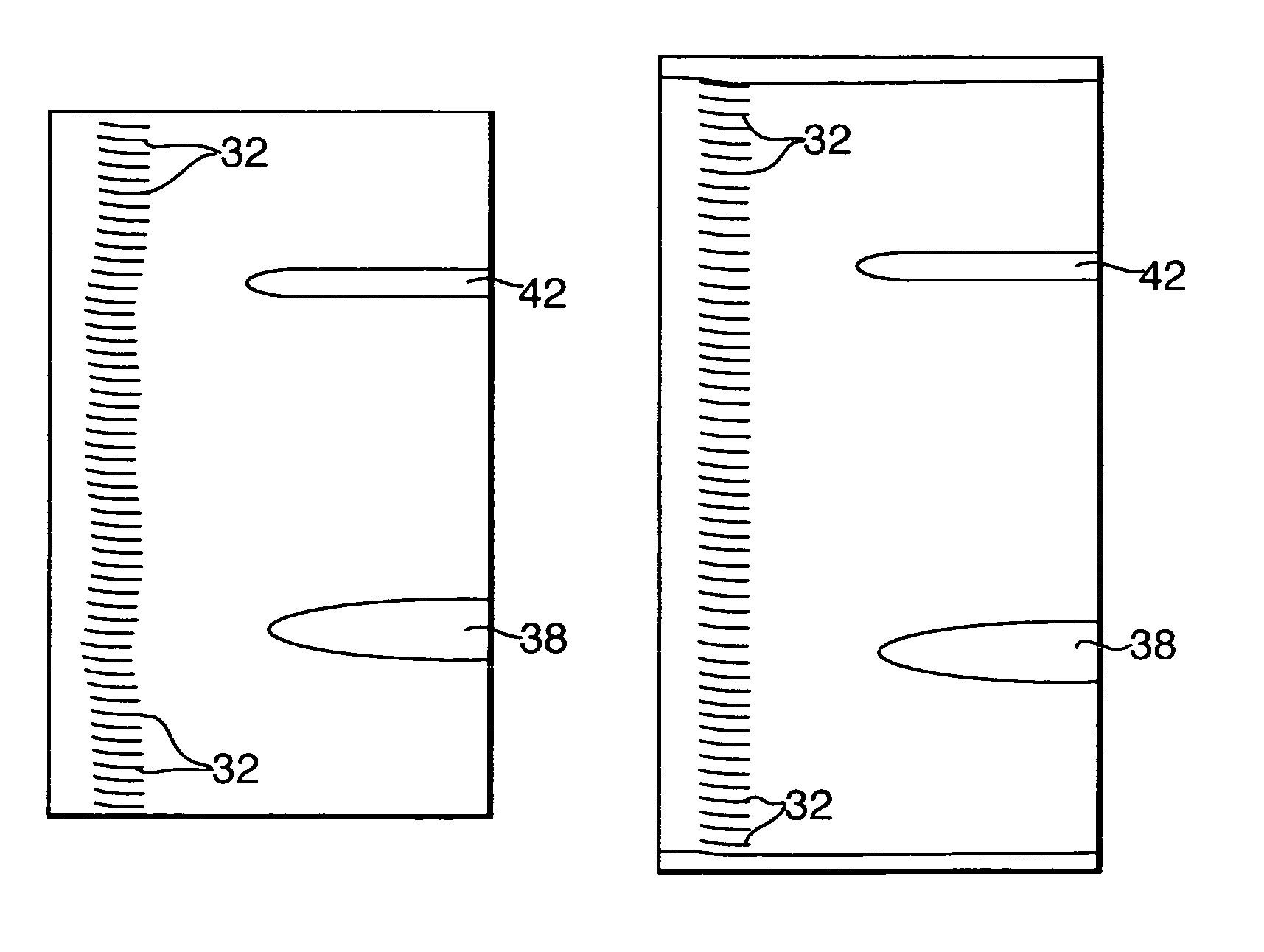
[0039]The fan section 14 comprises a fan rotor 24 arranged to carry a plurality of circumferentially arranged radially outwardly extending fan blades 26. The fan section 14 also comprises a fan casing 28, which encloses the fan rotor 24 and fan blades 26 and defines at least partially a fan duct 30. A plurality of circumferentially arranged fan outlet stator vanes 32 extend radially across the fan duct 30 between the fan casing 28 and a core engine casing 34. The fan outlet stator vanes 32 direct the airflow through the fan duct 30 to the fan duct outlet 36.

[0...


PUM


Abstract

A stator vane assembly for a turbomachine comprising a plurality of circumferentially arranged stator vanes (32), the axial position of the stator vanes (32) and / or the pitch angle circumferentially between adjacent stator vanes (32) is varied circumferentially around the stator vane assembly. The stator vane assembly reduces the pressure distortion upstream of the fan outlet stator vanes (32), reduces the circumferential pressure variation and this reduces blade forced response excitation, noise generation and aerodynamic losses.

Description

FIELD OF THE INVENTION[0001]The present invention relates to generally to a stator vane assembly for a turbomachine, particularly to a stator vane assembly for a gas turbine engine.[0002]Turbomachine aerofoils are susceptible to non-uniform flows generated by inlet distortion, wakes and pressure disturbances from adjacent rows of aerofoils.BACKGROUND OF THE INVENTION[0003]A turbofan gas turbine engine comprises a fan carrying a plurality of circumferentially spaced radially extending fan blades arranged to rotate within a fan duct defined by a fan casing. The fan casing is supported from a core engine casing by struts extending radially across the fan duct from the fan casing to the core engine casing and the engine is carried by a pylon which is secured to the core engine casing. The pressure non-uniformity is particularly strong in the fan duct due to the pylon and struts which extend radially across the fan duct and also due to a fairing for a radial drive shaft which extends rad...

Claims


Application Information

Patent Timeline
Patent Type & Authority Patents(United States)
IPC IPC(8): F01D9/00F01D5/14F01D9/04F04D29/54
CPCF01D5/142F01D9/041F04D29/544F04D29/666F04D29/541F04D29/542
Inventor SHAHPAR, SHAHROKH
Owner ROLLS ROYCE PLC
Why Eureka
Try Eureka