Gas ejector, electronic device, and gas-ejecting method

a gas ejector and electronic device technology, applied in the direction of pump parameters, pump details, piston pumps, etc., can solve the problems of increasing the quantity of heat generated, noise generation, and heat not being effectively released from the discharging fin, so as to inhibit the noise

Inactive Publication Date: 2009-09-03
SONY CORP
View PDF11 Cites 32 Cited by
  • Summary
  • Abstract
  • Description
  • Claims
  • Application Information

AI Technical Summary

Benefits of technology

[0033]As described above, according to the present invention, heat generated fro

Problems solved by technology

Hitherto, increase in the quantity of heat generated from a heater such as an IC (integrated circuit) due to a higher performance of a PC (personal computer) causes a problem, and a variety of heat dissipation methods are proposed or commercialized.
Unfortunately, forceful circulation by such a fan generates a temperature boundary layer on the surface of a downstream part of the dissipation fin causes a problem that heat cannot be effectively released from the dissipation fin.
In order to solve such a problem, although increasing the wind speed of the fan so as to make the temperature boundary layer

Method used


Image

  • Gas ejector, electronic device, and gas-ejecting method
  • Gas ejector, electronic device, and gas-ejecting method
  • Gas ejector, electronic device, and gas-ejecting method

Examples


Embodiment Construction

[0051]Embodiments of the present invention will be described with reference to the drawings.

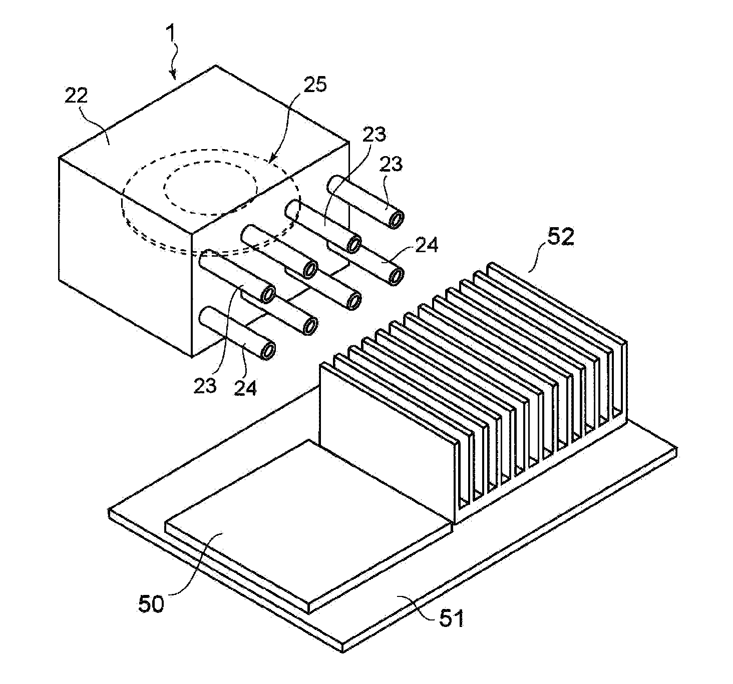
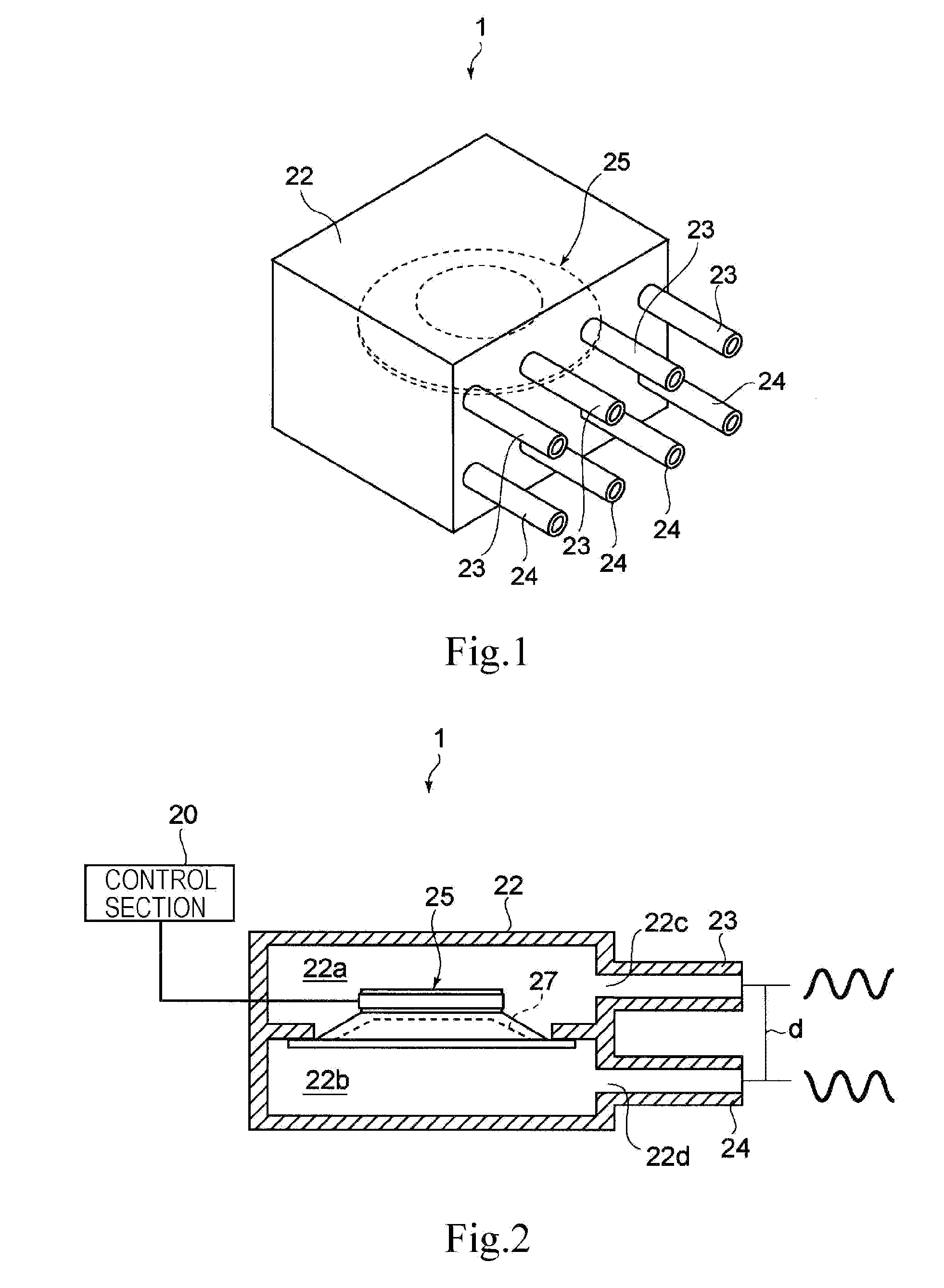
[0052]FIG. 1 is a perspective view of a gas ejector according to one embodiment of the present invention. FIG. 2 is a sectional view of the gas ejector.

[0053]A gas ejector 1 includes a single housing 22. The housing 22 has a vibrator 25 arranged therein, and the inside of the housing 22 is partitioned into two chambers 22a and 22b by the vibrator 25. The chambers 22a and 22b contain air, for example. The housing 22 has pluralities of opening sections 22c and 22d formed therein so as to allow the chambers 22a and 22b partitioned as described above to respectively communicate with the outside of the housing 22. In this case, the numbers of the opening sections 22c and 22d are the same as each other. The number of the opening sections 22c (22d) may be a single. The opening sections 22c and 22d respectively have nozzles 23 and 24 disposed therein, capable of ejecting air contained in the chambers...


PUM


Abstract

A gas ejector capable of effectively dissipating heat generated from a heater while inhibiting noise generation as little as possible, an electronic device equipped with the gas ejector, and a gas-ejecting method are offered. A gas ejector (1) according to the present invention includes a vibrator (25) and ejects gas in a form of a pulsating flow such that vibration of the vibrator allows sound waves respectively generated upon ejection of the gas ejected from nozzles (23) and (24) to deaden out each other. Also, a control section (20) optimizes the frequency of the vibrator (25), hence, by increasing the gas ejection quantity as much as possible while inhibiting noise generation, heat of a heater is effectively dissipated.

Description

TECHNICAL FIELD[0001]The present invention relates to a gas ejector configured to eject gas so as to dissipate heat generated by a heater, an electronic device equipped with the gas ejector, and a gas-ejecting method.BACKGROUND ART[0002]Hitherto, increase in the quantity of heat generated from a heater such as an IC (integrated circuit) due to a higher performance of a PC (personal computer) causes a problem, and a variety of heat dissipation methods are proposed or commercialized. With one of the methods for dissipating the heat, by arranging a heat dissipation fin composed of metal such as aluminum to contact with the IC, heat is conducted from the IC to the fin so as to be dissipated. Also, with another one of the methods, by employing a fan, hot air in a housing of, e.g., a PC is forcefully repelled, low-temperature circumambient air is introduced to the surrounding of the heater so as to achieve heat dissipation. With another one of the methods, by employing a dissipation fin a...

Claims


Application Information

Patent Timeline
IPC IPC(8): H05K7/20F28D21/00F04B45/04F04B45/047F04F7/00H01L23/467
CPCF04F7/00H01L23/467H05K7/20172H01L2924/0002H01L2924/00F04B35/04F04B53/001F04B53/16F04B2201/0802F05B2210/12
Inventor ISHIKAWA, HIROICHIMUKASA, TOMOHARU
Owner SONY CORP
Why Eureka
Try Eureka