Re-entrant cavity fluorescent lamp system

a fluorescent lamp and cavity technology, applied in the field of fluorescent lamps, can solve the problems of insufficient rf shielding for some uses, significant problems in producing higher lumen, and difficult hurdles for conventional electroded fluorescent lamps, and achieve the effect of superior rf shielding

Inactive Publication Date: 2006-10-10
OSRAM SYLVANIA INC
View PDF16 Cites 31 Cited by
  • Summary
  • Abstract
  • Description
  • Claims
  • Application Information

AI Technical Summary

Benefits of technology

[0006]It is another object of the invention to enhance the operation of electrodeless fluorescent lamps.
[0007]Yet another object of the invention is a fluorescent lamp having better amalgam temperature control.
[0009]These objects are accomplished, in one aspect of the invention, by the provision of an electrodeless fluorescent lamp having a burner, a ballast housing containing a ballast and a base for connection to a power supply. A reentrant cavity is provided in the burner and an amalgam receptacle is in communication with the burner. A housing cap connects the burner to the ballast housing and there is an EMI cup formed as part of the ballast housing. The EMI cup has a bottom portion and a cap with an aperture therein closing an upper portion. The amalgam receptacle extends through the aperture and into the ballast housing, which helps to regulate the amalgam temperature. The ballast housing provides superior RF shielding allowing multiple uses of the lamp in places previously unavailable.

Problems solved by technology

As market forces call for more efficient fluorescent lamps to be smaller and more incandescent in shape, conventional electroded fluorescent lamp faces difficult hurdles.
Higher temperatures lead to significant problems in producing higher lumen (e.g., >15 W, 800 lumen), A-shaped electroded systems.
The latter type of electrodeless discharge lamp works well generally; however, it presents some problems with heat, inadequate RF shielding for some uses, and inadequate temperature control for the amalgam.

Method used


Image

  • Re-entrant cavity fluorescent lamp system
  • Re-entrant cavity fluorescent lamp system
  • Re-entrant cavity fluorescent lamp system

Examples


Embodiment Construction

[0012]For a better understanding of the present invention, together with other and further objects, advantages and capabilities thereof, reference is made to the following disclosure and appended claims in conjunction with the above-described drawings.

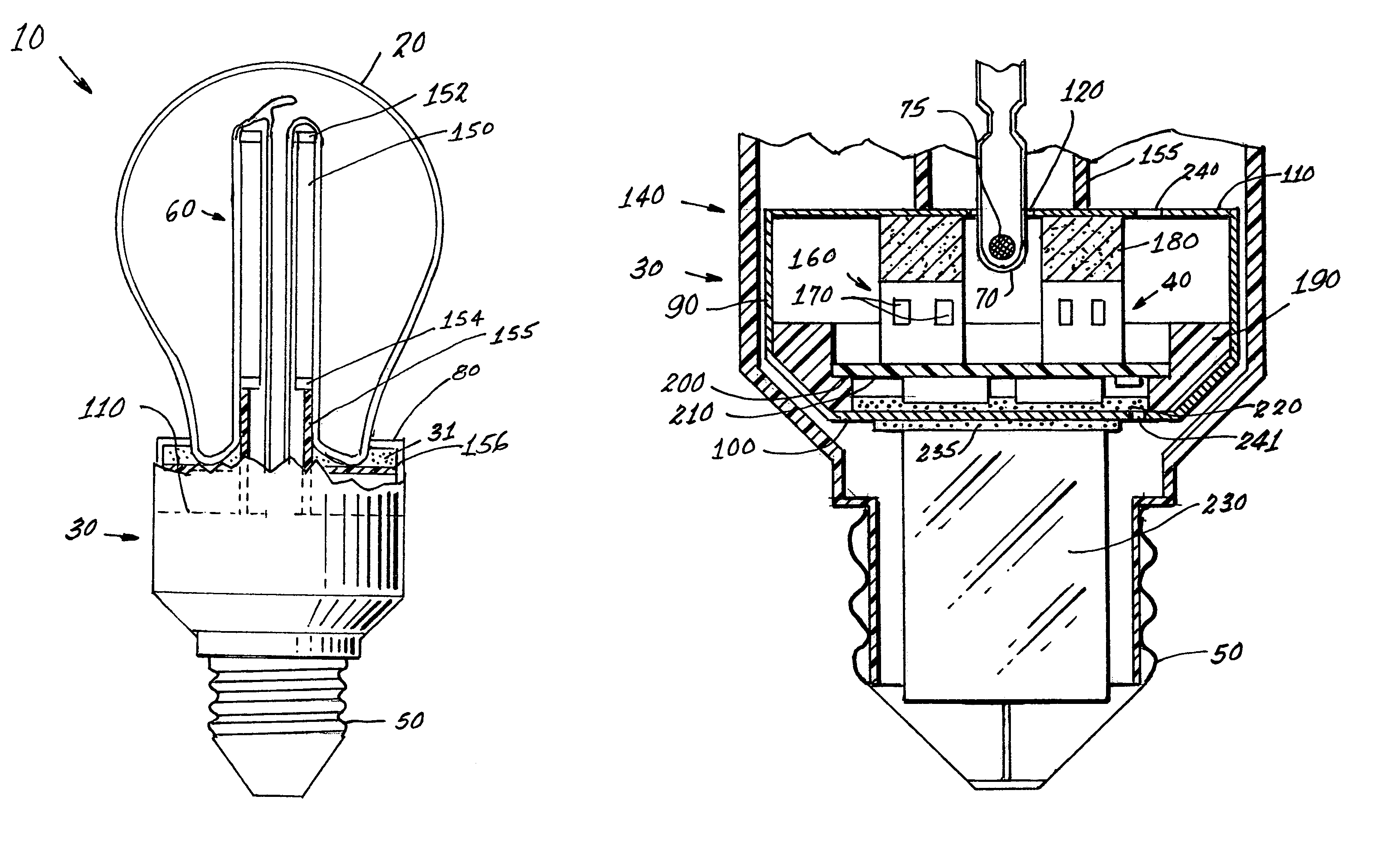
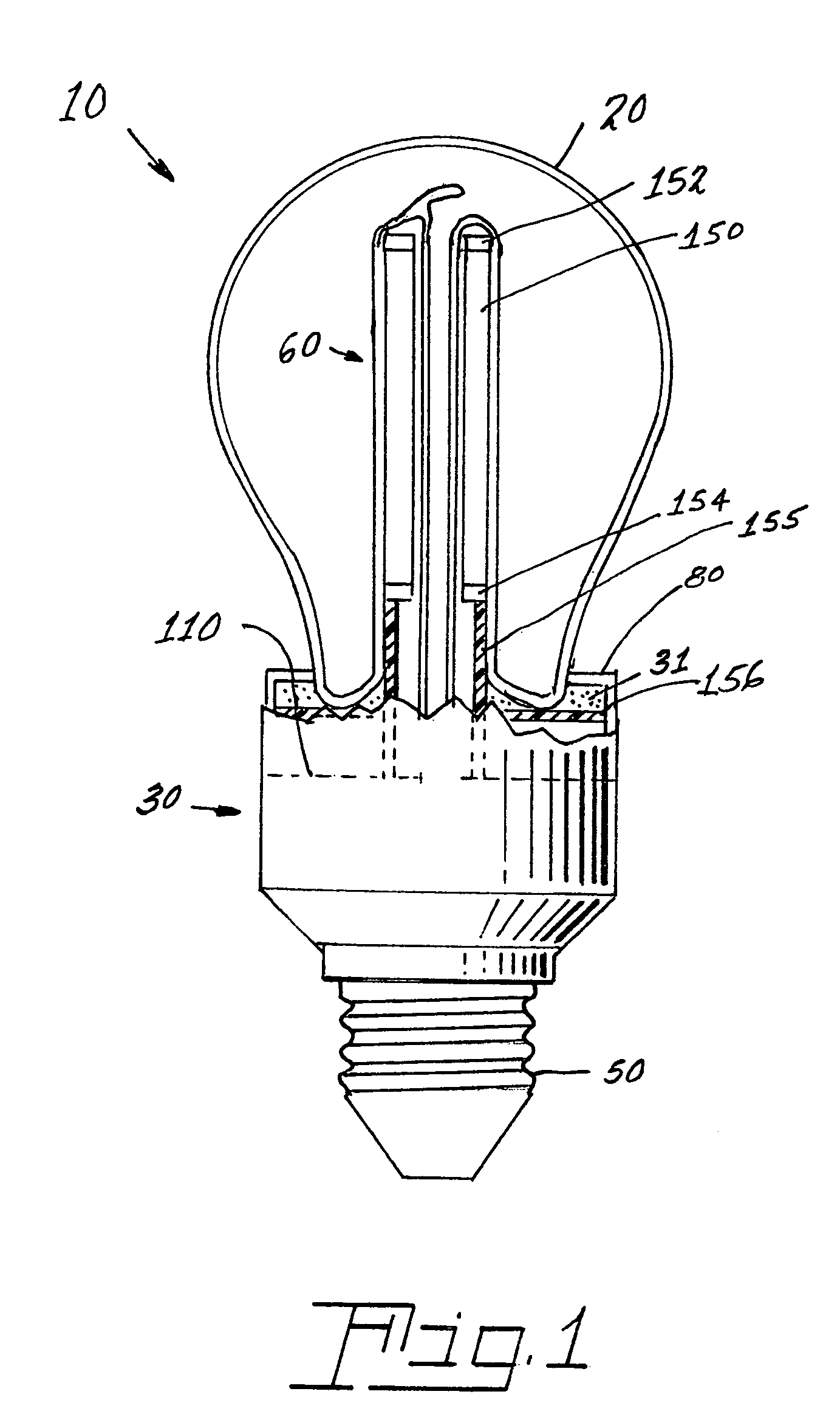
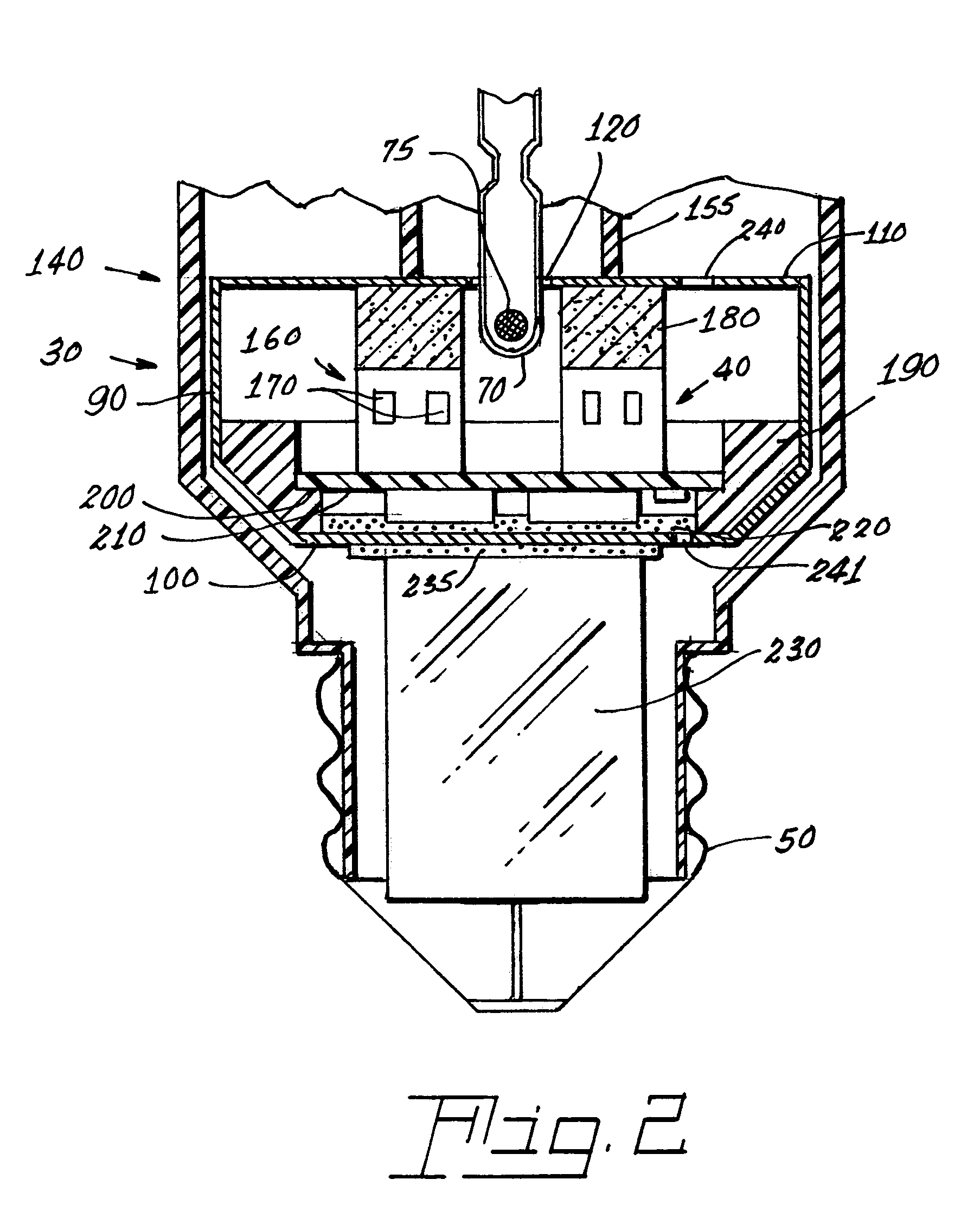
[0013]Referring now to the drawings with greater particularity, there is shown in FIG. 1 an electrodeless fluorescent lamp 10 having a burner 20, a ballast housing 30 containing a ballast 40 and a screw base 50 for connection to a power supply. A reentrant cavity 60 is formed in the burner 20 and an amalgam receptacle 70 containing amalgam 75 is formed as a part of the reentrant portion and in communication with the burner 20. A housing cap 80, formed of a suitable plastic, connects the burner 20 to the ballast housing 30 and a suitable adhesive 31 fixes the burner to the housing cap 80. An EMI cup 90 is formed as an insert to fit into the ballast housing 30, which also is formed of a suitable plastic, and has a bottom portion 100 and ...


PUM


Abstract

An electrodeless fluorescent lamp (10) having a burner (20), a ballast housing (30) containing a ballast (40) and a screw base (50) for connection to a power supply. A reentrant cavity (60) is formed in the burner (20) and an amalgam receptacle (70) containing amalgam (75) is formed as a part of the reentrant portion and in communication with the burner (20). A housing cap (80), formed of a suitable plastic, connects the burner (20) to the ballast housing (30) and a suitable adhesive (31) fixes the burner to the housing cap (80). An EMI cup (90) is formed as an insert to fit into the ballast housing (30), which also is formed of a suitable plastic, and has a bottom portion (100) and an EMI cap (110) with an aperture (120) therein closing an upper portion (140). The EMI cup (90) and the EMI cap (110) are preferably formed from 0.5 mm brass. The amalgam receptacle (70) extends through the aperture (120) and into the cup (90). For a fixed amalgam position, changing the aperture size allows adjustment of the amalgam tip temperature, and thus, allows control of the system lumen output, efficacy, CCT and CRI, all of which are dependent on the amalgam temperature.

Description

CROSS REFERENCE TO RELATED APPLICATIONS[0001]This application claims priority from Provisional Patent Application Ser. No. 60 / 519,143 filed Nov. 12, 2003.TECHNICAL FIELD[0002]This invention relates to fluorescent lamps and more particularly to electrodeless fluorescent lamps. Still more particularly, it relates to such lamps having a reentrant cavity.BACKGROUND ART[0003]As market forces call for more efficient fluorescent lamps to be smaller and more incandescent in shape, conventional electroded fluorescent lamp faces difficult hurdles. The A-shaped bulb that covers conventional electroded discharges causes an approximately 8% lumen decrease due to reflection loss. The gas separation between the electroded lamp's tubular phosphor layer (where the heat is generated) and the A-shaped outer covering (where heat escapes the system) leads to inherently higher system temperatures. Higher temperatures lead to significant problems in producing higher lumen (e.g., >15 W, 800 lumen), A-sh...

Claims


Application Information

Patent Timeline
Patent Type & Authority Patents(United States)
IPC IPC(8): H01J1/62H01J61/28H01J61/56H01J65/04
CPCH01J61/28H01J65/048H01J61/56H01J61/523H01J5/54
Inventor GODYAK, VALERY A.ALEXANDROVICH, BENJAMIN M.SAPOZHNIKOV, ALEXANDER A.HUTCHERSON, KENNETH R.
Owner OSRAM SYLVANIA INC
Why Eureka
Try Eureka