
Column/row redundancy architecture using latches programmed from a look up table

a look up table and latch technology, applied in the field of memory devices, can solve the problems of limited number of defective columns which can be repaired, and consume die space, and achieve the effect of saving die area

Active Publication Date: 2006-10-10
MICRON TECH INC
View PDF17 Cites 21 Cited by
  • Summary
  • Abstract
  • Description
  • Claims
  • Application Information

AI Technical Summary

Benefits of technology

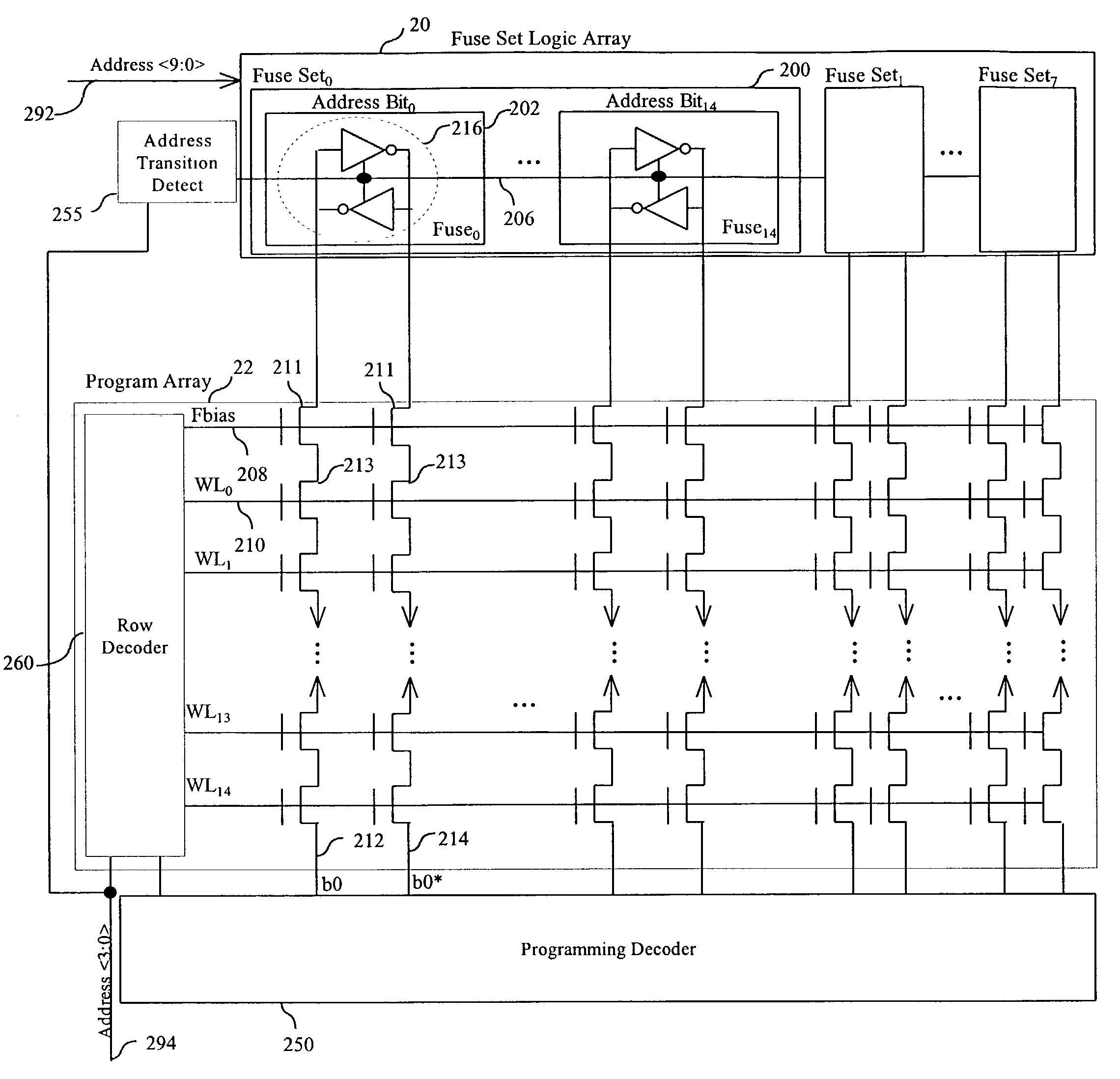
[0006]The present invention implements column or row redundancy using a single group of reloadable latches and associated XOR logic, which upon a change in an incoming address dynamically reloads the latch with new redundancy information associated with the specific incoming addresses. Since the latches are reloaded with new redundancy addresses for each incoming address transition, a given capacity of redundant columns or rows can be accommodated with fewer fuse circuit elements. This provides for considerable die area savings compared to traditional implementations of column or row redundancy.

Problems solved by technology

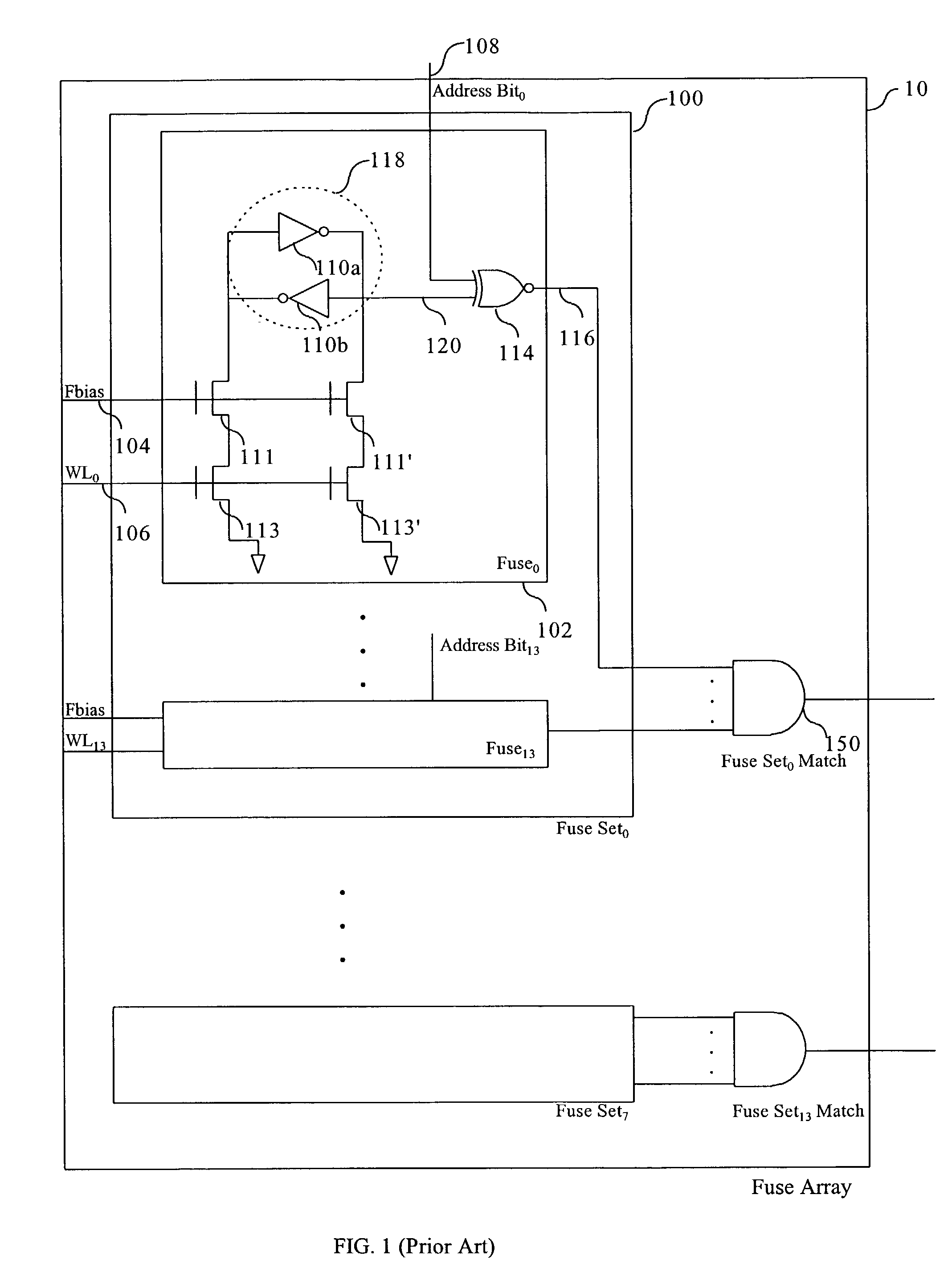
The problem with this approach is that since each fuse set 100 is permanently set with the address of a defective column, the number of defective columns which can be repaired is limited by the number of fuse sets 100 fabricated on the die.
Additionally, fuse arrays 10 consume die space.

Method used


Image

  • Column/row redundancy architecture using latches programmed from a look up table
  • Column/row redundancy architecture using latches programmed from a look up table
  • Column/row redundancy architecture using latches programmed from a look up table

Examples


Embodiment Construction

[0016]The present invention can be used for substitution of a redundant memory line containing memory elements for a defective memory line containing memory elements. The invention can be used to substitute a redundant column line for a defective column line, or for substitution of a redundant row line for a defective row line in a memory device. However, to simplify the description, the invention will be described in connection with the substitution of a redundant column for a defective global column in a flash memory device. It should be understood, however, that the invention can be used to substitute a redundant column for a defective column or a redundant row for a defective row in any type of memory device.

[0017]During memory device testing when a defective column is detected its address is stored in a lookup table, where the column maybe a global column. After testing, when the memory array is in use, a memory access to an identified defective column is remapped to a redundan...


PUM


Abstract

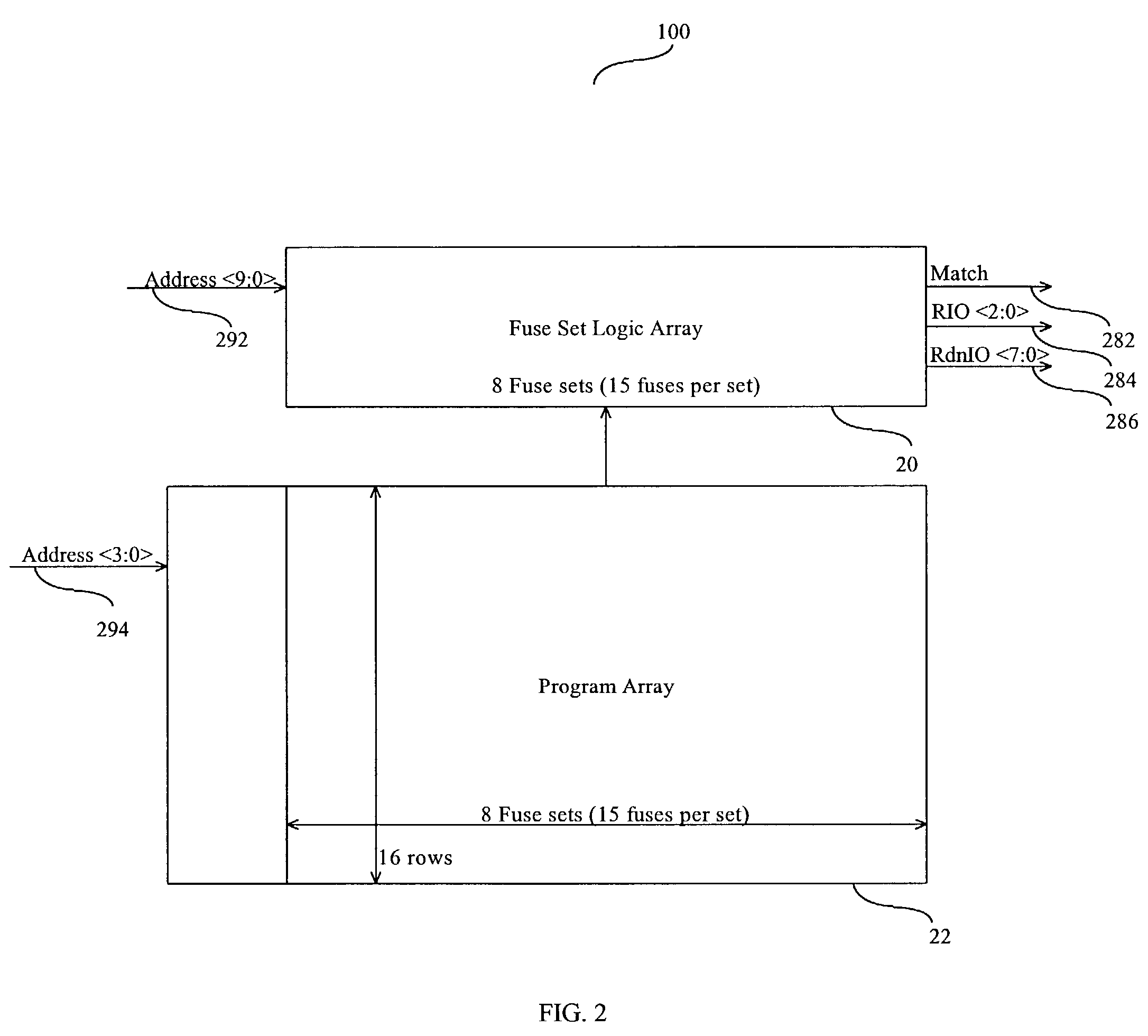
A scheme for defective memory column or row substitution is disclosed which uses a programmable look-up table to store new addresses for column selection when certain column or row addresses are received. The new addresses are loaded into a programmable fuse latch each time an address transition is detected in the input address.

Description

FIELD OF THE INVENTION[0001]This invention relates to the field of memory devices and more particularly, to a column / row redundancy architecture for semiconductor memory.BACKGROUND OF THE INVENTION[0002]As memory chip manufacturers strive to decrease die size, and increase capacity and speed they must contend with an increased percentage of defective, or faulty memory cells. Different approaches have been taken to overcome detected memory cell defects. One approach has been to “repair” out a defective memory column or row by “flagging” the defective column or row and using redundant columns or rows of memory cells that are substituted for defective columns or rows. A defective region is marked as defective by blowing fuses, or anti-fuses, or lasers are used to etch circuits, to set latches which remap the defective column or row to a non-defective fully-operable redundant column or row. With this re-mapping, attempts to address the defective column or row will be redirected to addre...

Claims


Application Information

Patent Timeline
Patent Type & Authority Patents(United States)
IPC IPC(8): G11C7/00G06F12/10
CPCG11C29/76G11C29/789
Inventor LAKHANI, VINODLOUIE, BENJAMIN
Owner MICRON TECH INC
Learn More