Head immobilizer

a head and head technology, applied in the field of head immobilization equipment, can solve the problems of not being able to disclose or suggest an immobilization equipment in these patents, and achieve the effects of promoting proper immobilization technique, minimizing movement, and improving the x-ray transparency of the injured person's head

Inactive Publication Date: 2006-10-17
LAERDAL MEDICAL CORP
View PDF49 Cites 19 Cited by
  • Summary
  • Abstract
  • Description
  • Claims
  • Application Information

AI Technical Summary

Benefits of technology

[0038]Two side head blocks are each removably attached to the headboard using a plunger-type lock that engages an elongated slot on a respective side of the headboard. These locks are engaged to the slots of the headboard through separate elongated slots in the head blocks, which may be aligned perpendicularly to the slots of the headboard. Advantageously, the head blocks may be adjusted by moving the engagement of the locks along a set of slots in the headboard and a set of slots in the head blocks, respectively. In addition, the head blocks may be rotated around the locks. Consequently, the present invention allows the blocks to be located at any point on the base within a predetermined limit of motion. The head blocks are, thus, adjustable so as to accommodate the various size features of a particular patient while promoting proper immobilization technique by minimizing movement of, and possible trauma to, the cervical spine of the patient.
[0039]Each head block has a universal configuration such that there is no difference between a left and a right head block. When attached to the headboard, each head block includes an upright planar portion with a soft material (foam pad) attached thereto for fitting a side of the injured person's head and a horizontal portion that includes the aforementioned slot for engaging the headboard. The upright planar portion includes an arch opening that exposes the side of the injured person's head so as to allow access thereto for ...

Problems solved by technology

None of these patents, however, discloses or suggests an immobilization apparatus that provides for ease of adjustability without removal of pa...

Method used


Image

  • Head immobilizer
  • Head immobilizer
  • Head immobilizer

Examples


Embodiment Construction

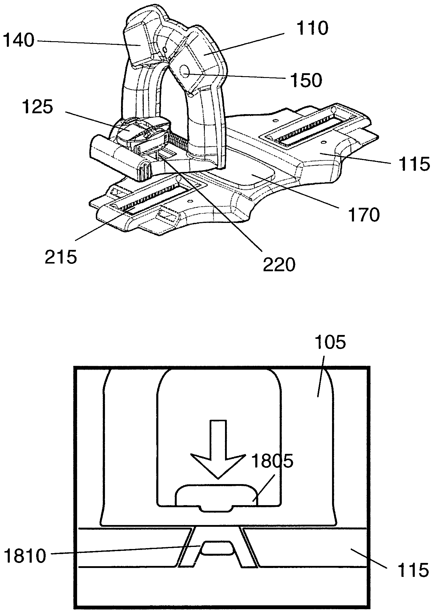
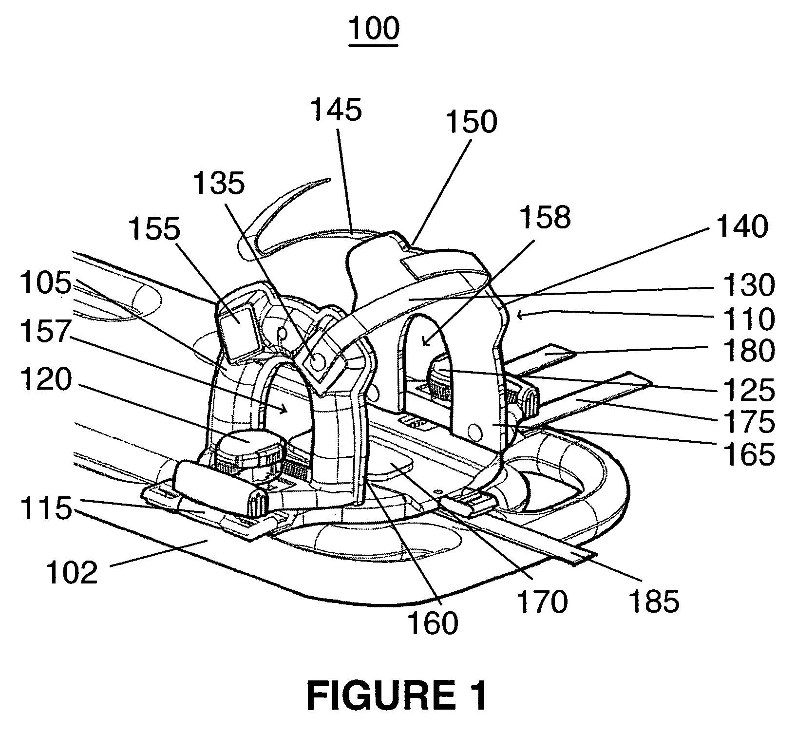
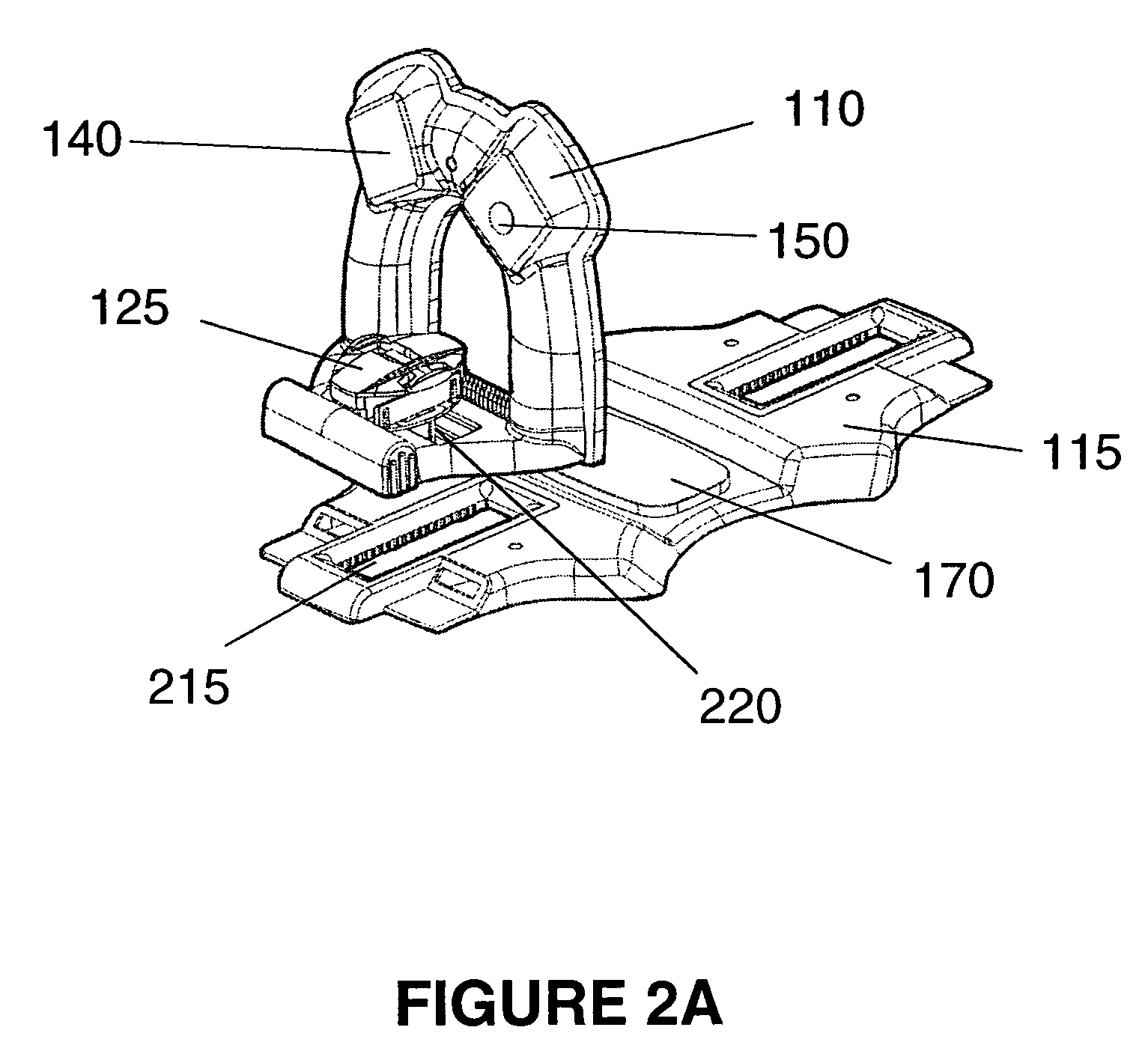
[0070]FIG. 1 depicts an assembled head immobilization apparatus 100 for attaching a spine board 102 in accordance with an embodiment of the invention. As illustrated in FIG. 1, head immobilization apparatus 100 comprises two head blocks 105 and 110 placed on either side of an injured person's head (see FIG. 11). It is noted that, in accordance with an embodiment of the invention, blocks 105 and 110 are of a uniform design so that they may be interchanged with each other on either side of the injured person's head. It is, thus, noted that the following description and corresponding Figures regarding either block 105 and 110 may be applied to other, and that duplicate description may be omitted.

[0071]Blocks 105 and 110 are fixed to a headboard (or base) 115 for supporting the back of the injured person's head by pressing down on plunger-type locks 120 and 125. Blocks 105 and 110 can be released for readjustment or removal by depressing a respective lever on lock members 120 and 125, w...


PUM


Abstract

A base headboard for supporting the back of an injured person's head has an elongated slot with teeth racks disposed on either side of the injured person's head. The headboard also comprises straps for attaching to a spine board. Two side head blocks are removably attached to the headboard using plunger-type locks that engage an elongated slot on each side of a center portion of the headboard. Each lock is engaged to a slot of the headboard through a separate elongated slot in the corresponding head block. Advantageously, a head block may be adjusted by moving the engagement of the lock along each independent slot in the headboard and head block, respectively. In addition, a head block may be rotated around its lock. Head pads and straps, and pads and straps for cervical collars that come into contact with a patient may be replaceable and packaged in a kit, thereby allowing the durable components (such as head blocks and headboard) to be reused indefinitely and reducing cleaning costs and minimizing exposure to pathogens. Such a kit of replaceable parts may also reduce material waste compared having all disposable components without any durable components (i.e. head immobilizers).

Description

CROSS REFERENCE TO RELATED APPLICATIONS[0001]This application is a continuation-in-part application to U.S. patent application Ser. No. 09 / 741,297, filed Dec. 19, 2000, now U.S. Pat. No. 6,637,057.FIELD OF THE INVENTION[0002]The present invention relates generally to an improved head immobilization apparatus that is attachable to, and detachable from, a spine board of the type employed by emergency medical personnel for transporting injured persons.BACKGROUND OF THE INVENTION[0003]Spine boards have been used by physicians and emergency medical personnel for a number of years in the transport of injured or incapacitated persons. Particular care and attention is needed for the immobilization of the head and neck of an injured person being transported. Head and cervical spine immobilization is necessary to prevent possible neck (cervical spine) injuries from being exacerbated during transport. It is desirable that such immobilization be performed quickly and properly after an injured p...

Claims


Application Information

Patent Timeline
IPC IPC(8): A61G1/04A61F5/37A61FA61F5/055A61F5/058A61G1/044A61G7/07
CPCA61F5/055A61F5/05883A61G1/04A61G1/044A61G7/072
Inventor TRAUT, JAMESPHILLIPS, SEAN
Owner LAERDAL MEDICAL CORP
Why Eureka
Try Eureka