Security barrier reinforcing system

a technology of reinforcement and security barrier, applied in the direction of fencing, ways, buildings, etc., can solve the problems of reducing the benefit of reinforcement in resisting higher impact crashes, heavy weight and complex systems, and not providing protection against cutting action of pipe ends, etc., to reduce damage potential of cables, improve bollards, and more evenly distributed loading

Active Publication Date: 2006-10-17
GLOBAL GRAB TECH INC
View PDF26 Cites 23 Cited by
  • Summary
  • Abstract
  • Description
  • Claims
  • Application Information

AI Technical Summary

Benefits of technology

[0010]This invention provides an improved system to upgrade a preexisting swinging or sliding gate or other barrier section to an effective anti-ram vehicle barrier by attaching to the barrier a reinforcing structural member and cable assembly that provides more evenly distributed loading and reduced damage potential to the cable. The invention also improves the bollards to catch the attached assembly by 1) increasing the strength of the catch hook and its attachment to the bollard and 2) providing for reinforcement positioning so that the bollards may be more easily installed properly.

Problems solved by technology

Similarly, these systems do not provide protection against cutting action of the pipe ends or the standoffs on the wire rope.
This system was heavier and more complex in that it required additional cable fittings, additional pipe, an additional row of catch hooks on the bollards, and more precise placement of the attachments to the gate.
Installation of reinforcing steel in the bollards can be inconsistent, potentially reducing the benefit of the reinforcement in resisting higher impact crashes.
While numerous gates and barriers have been developed to stop or ensnare vehicles, patented devices to modify or strengthen existing gates and barriers are uncommon.
The Fischer system, however, requires anchors with a spring-loaded locking mechanism, and does not provide a passive mechanism such as trapping the bollard catch to arrest forward motion.

Method used


Image

  • Security barrier reinforcing system
  • Security barrier reinforcing system
  • Security barrier reinforcing system

Examples


Embodiment Construction

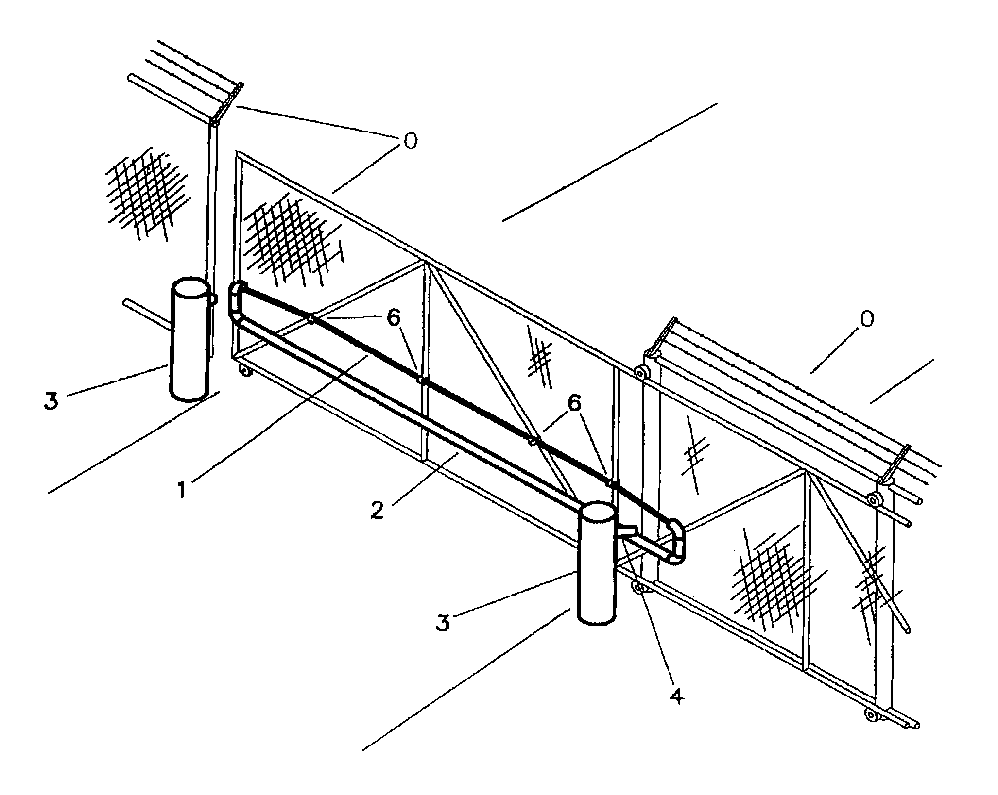
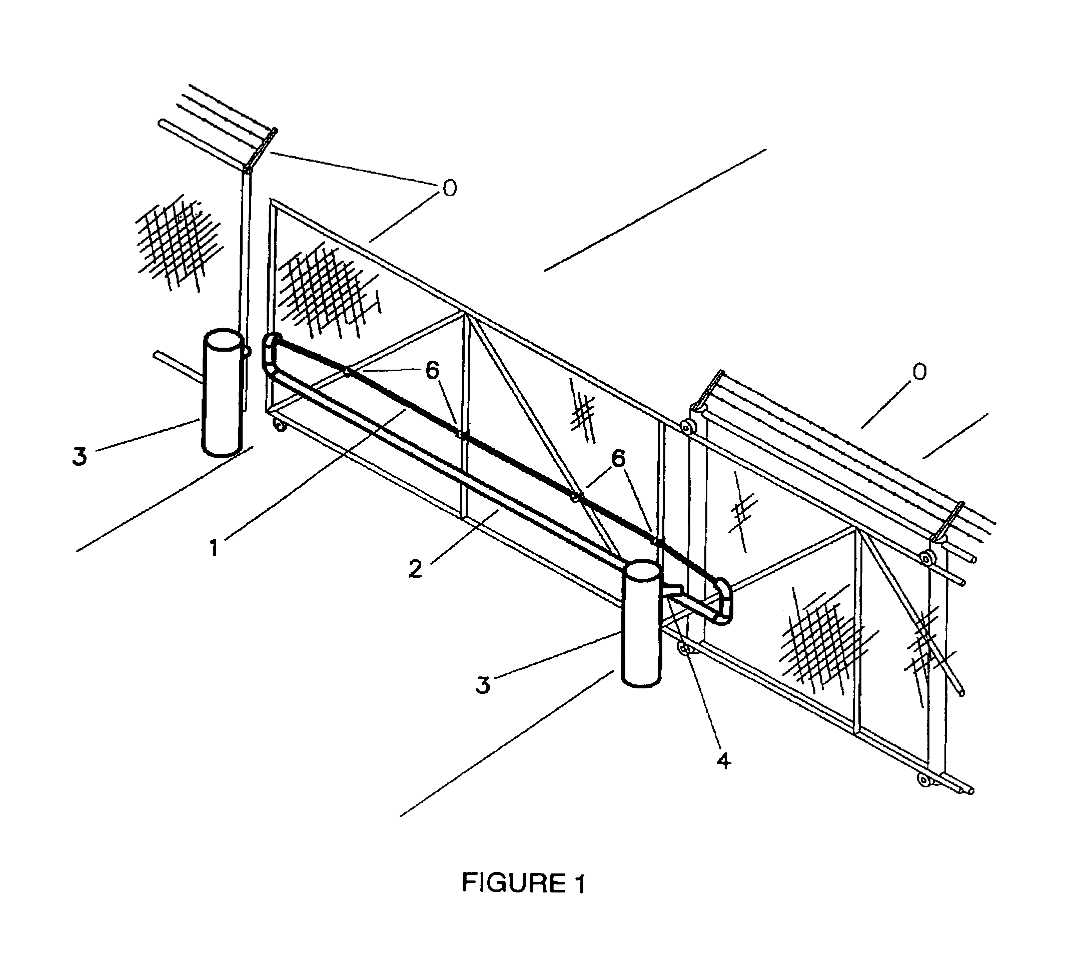
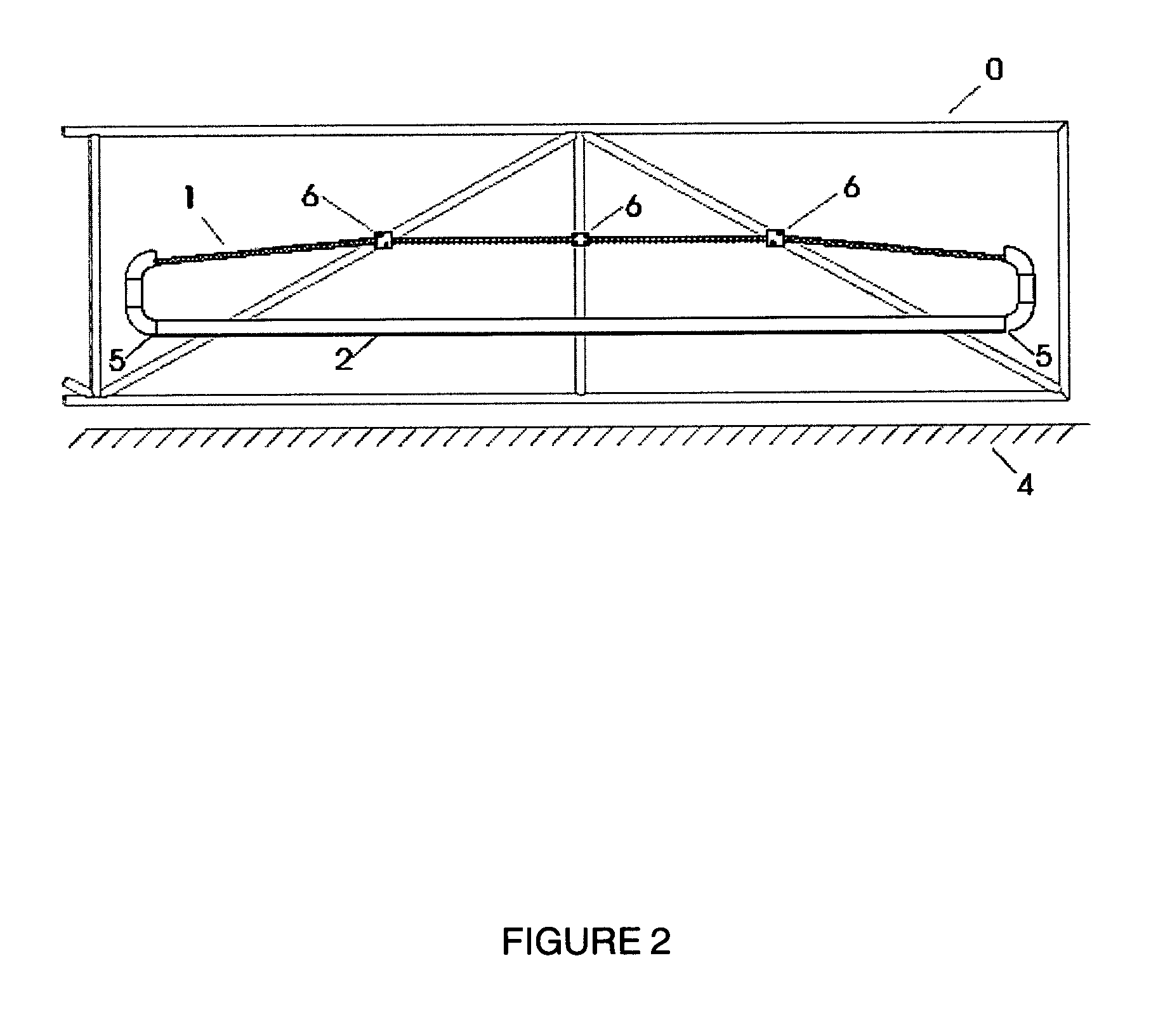
[0017]An overview of the preferred embodiment (or best mode) of the invention is shown in FIG. 1. This embodiment is based on a twenty foot wide drive, with an intent to stop a fifteen-thousand pound vehicle traveling at fifty miles per hour. In the preferred embodiment, the cable (1) is a 1½″ multistrand steel cable, but any cable of sufficient strength to provide the required stopping force would suffice. The invention consists of an assembly of flexible cable (1) routed through a structural member (2) that has joints and ends finished so that when impacted, the force of the impact is absorbed by both the structural member and the cable, the force is distributed with regard to the cable and no surface provides a cutting action on the cable. This assembly shall be of sufficient width to span the barrier or gate section to be protected (O) and shall be attachable to an existing barrier or gate in such a way as not to impede the regular operation of said barrier or gate. Additionally...


PUM


Abstract

A system for upgrading new and existing gates or barriers to provide improved crash barrier rating. This system comprises a reinforcing attachment to the gate or barrier and improved reinforced bollards with catch hooks to absorb the energy of impact from a vehicle. The reinforcing attachment is an arrangement of cable and structural members that provide for increased reinforcement by ensuring that the load is distributed on the cable to minimize the risk of breakthrough as a result of cable failure. The bollards have been improved by strengthening the catch hook attachments and adding reinforcement positioning elements to facilitate proper assembly.

Description

BACKGROUND[0001]With heightened security requirements at facilities across the country and overseas, the need has become apparent for a device that can easily upgrade gates and fences to meet necessary crash barrier requirements. A simple device in use at Argonne National Laboratory since the mid-1980s provides an approach that has been improved with this invention. That device is believed to be the “novel gate barrier” determined to be in the public domain according to a letter on Argonne National Laboratory letterhead from E. Gale Pewitt, Chief Operations Officer, to Mr. David Fitzgerald at the Tennessee Innovation Center, dated Sep. 22, 1987. The “novel gate barrier” is simply a straight steel pipe with a wire rope cable through it. The cable ends are connected so that the cable forms a loop, part inside and part outside the pipe. The pipe is attached to the fence and the cable loop hangs below the pipe. A variation at another gate apparently has metal standoffs welded to the pip...

Claims


Application Information

Patent Timeline
Patent Type & Authority Patents(United States)
IPC IPC(8): E01F13/00E01F13/04
CPCE01F13/048
Inventor ANDERSON, JOE W.LIGHT, MICHAEL W.KAMINSKY, VICTOR J.POWERS, JAMESSCHENK, RICHARD W.
Owner GLOBAL GRAB TECH INC
Why Eureka
Try Eureka