Band saw, band saw processing apparatus and band saw manufacturing method

a band saw and processing apparatus technology, applied in the field of band saws, can solve the problems of easy deformation and cracking troublesome and expensive process of coating the saw teeth, saw tooth bases and the like with hard materials, and the loss of cutting precision and cutting efficiency, so as to improve the effect of increasing improving the strength and rigidity of the saw body

Inactive Publication Date: 2006-10-17
YG MARUSHIMO MACHINE SAW
View PDF28 Cites 24 Cited by
  • Summary
  • Abstract
  • Description
  • Claims
  • Application Information

AI Technical Summary

Benefits of technology

[0027]According to this method of the present invention, because the strength and rigidity of the tooth base line area of the saw body are increased significantly, thereby improving the strength and rigidity of the saw body, the saw teeth and saw tooth bases. Therefore, the entire band saw can be strengthened more easily a

Problems solved by technology

When a conventional band saw is used continuously, the saw teeth undergo heat deformation or heat buckling due to cutting resistance or friction against the saw teeth, thereby causing the desired cutting precision and cutting efficiency to be lost and giving rise to the problem of so-called sawing bend.
In addition, stress due to cutting resistance against the saw teeth tends to become concentrated at the saw tooth bases, causing cracking.
To cope with these problems, it has been conceived to coat certain areas of the saw teeth, saw tooth bases and the like with a hard material at prescribed locations, as described in JP-A-1-188221 or JP-U-7-45012, for example, thereby increasing the rigidity of the saw teeth and saw tooth bases However, in the band saw described in the above documents, the process of coating the saw teeth, saw tooth bases and the like with a hard material is troublesome and expensive.
Further, since stress then becomes concentrated at the borders

Method used


Image

  • Band saw, band saw processing apparatus and band saw manufacturing method
  • Band saw, band saw processing apparatus and band saw manufacturing method
  • Band saw, band saw processing apparatus and band saw manufacturing method

Examples


example 1

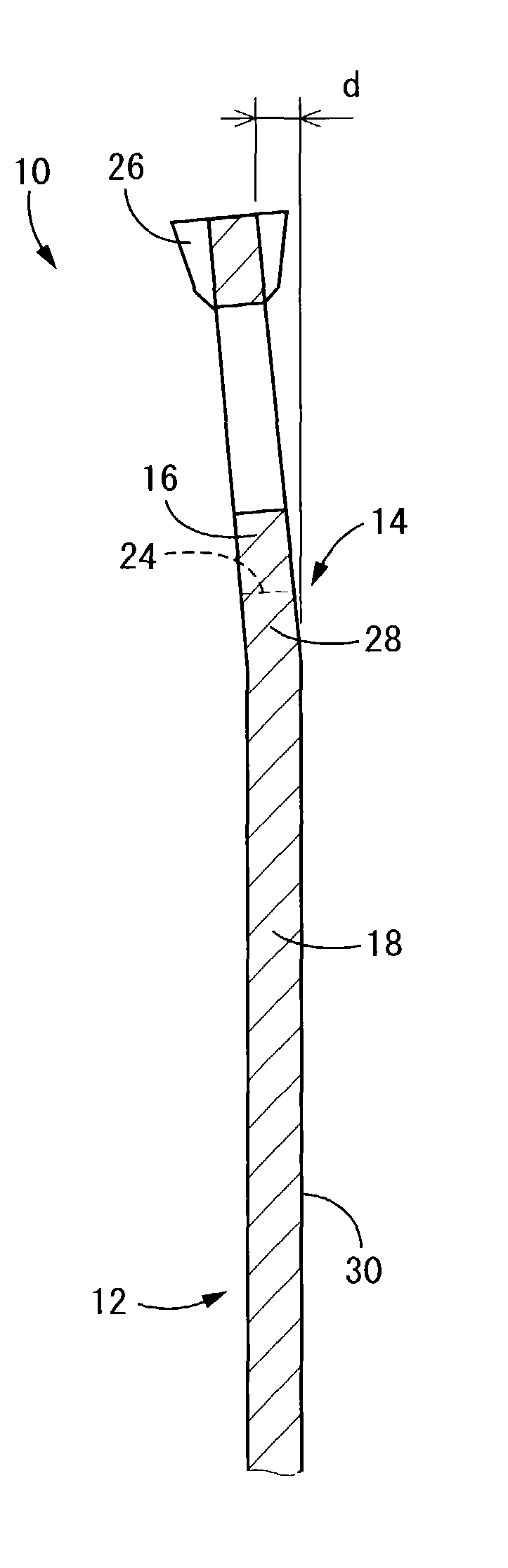
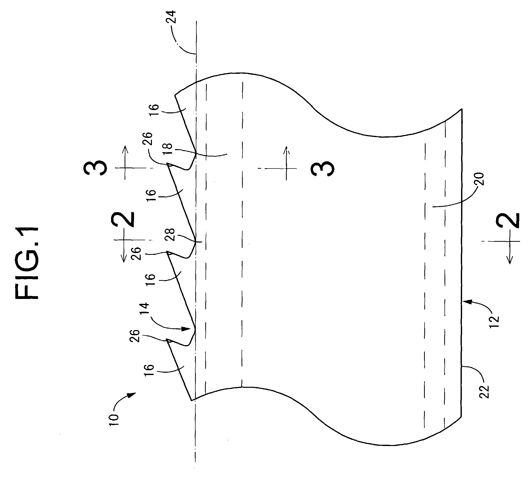
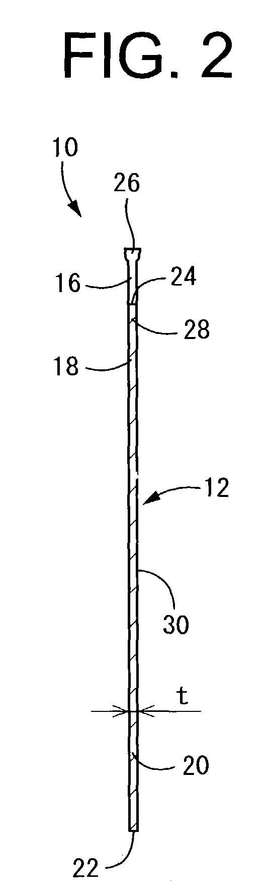
[0074]A band saw having a saw width of 125 mm, a saw blade thickness of 0.9 mm, a saw body length of 7250 mm, and a saw tooth pitch of 28 mm was produced. The tooth base side tension band of the saw body of this band saw was subjected to heat tensioning to achieve a tensioning degree of 28, and the top line area of the saw body was subjected to back-filling using a 75 cm-long back gauge where the back-filling amount (I) was 0.5 mm. In the Example 1, a pick-shaped projection was formed on the tip of each saw tooth with an initial width (w) of 1.8 mm, and the initial value for the amount of protrusion (d) of the tip of each saw tooth along the direction of the saw's thickness relative to the surface of the saw body was set to 0.06 mm. The band saw was then mounted to a band saw apparatus having a model number 1100 (43 elbow type) and a saw wheel rotation speed of 766 rpm and driven to revolve. Saw material comprising a white cedar log with bark having an end diameter of 15–23 cm and 3...

examples 2 through 4

[0080]Three band saws having the same initial dimensions as the Example 1 were produced, and one was used for six months and deemed Example 2, one was used for nine months and deemed Example 3, and one was used for 11 months and deemed Example 4. In each of these Examples 2 through 4, as with the Example 1, the tooth base side tension band of the saw body was subjected to heat tensioning to achieve a tensioning degree of 28, and the top line area of the saw body was subjected to back-filling using a 75 cm-long back gauge where the back-filling amount (I) was 0.5 mm. The first through third processing sessions were carried out with regard to the Examples 2 through 4 in the same manner as in connection with the Example 1. After each session, the saw teeth and projections were polished, the projection width (w) and the saw tooth tip protrusion amount (d) were reset, and the time at which sawing bend occurred (i.e., the length of time that the saw could be used for processing) was measu...


PUM

PropertyMeasurementUnit
Thicknessaaaaaaaaaa
Lengthaaaaaaaaaa
Lengthaaaaaaaaaa

Abstract

A band saw includes a continuous saw body and multiple saw teeth provided on an edge portion of said saw body entirely. The edge portion of the saw body and the saw teeth are angled toward an inner side of the saw body by creating a bend near a tooth base line of the saw body. A band saw processing method and a method of manufacturing the band saw are also disclosed.

Description

INCORPORATED BY REFERENCE[0001]The disclosure of Japanese Patent Application No. 2002-184839 filed on Jun. 25, 2002 including the specification, drawings and abstract is incorporated herein by reference in its entirety.BACKGROUND OF THE INVENTION[0002]1. Field of the Invention[0003]The present invention relates generally to band saws installed on band saw apparatuses to be used in lumber processing, and more particularly to a band saw which is novel in construction and capable of eliminating or minimizing occurrence of sawing bends (deemed herein to include cutting bends) due to cutting resistance or friction generated between the saw band and a lumber.[0004]2. Description of the Related Art[0005]As is well known in the art, a band saw used for cutting lumber and the like has a construction wherein multiple saw teeth are formed on the edge portion of a continuous annular plate. By suspending the band saw around a pair of saw wheels mounted on a band saw apparatus and causing it to r...

Claims


Application Information

Patent Timeline
IPC IPC(8): B23D61/12B23D63/00B23D65/00B27B33/06
CPCB23D61/121B23D63/006B23D65/00Y10T83/707Y10T83/9317Y10T83/9319
Inventor SHIMOFURUTANI, TATSUO
Owner YG MARUSHIMO MACHINE SAW
Why Eureka
Try Eureka