Tripod type constant velocity universal joint

a constant velocity, universal joint technology, applied in the direction of yielding couplings, rotary machine parts, couplings, etc., can solve the problems of increasing rotation durability, generating shudder or degradation of rotation durability, etc., and achieve high rotation durability

Active Publication Date: 2006-10-17
NTN CORP
View PDF6 Cites 14 Cited by
  • Summary
  • Abstract
  • Description
  • Claims
  • Application Information

AI Technical Summary

Benefits of technology

[0012]It is an object of the present invention to provide a tripod type constant velocity universal joint that can reduce the 3rd order cyclic axial force so as to suppress generation of shudder and that has high rotation durability.
[0016]The aforementioned tripod type constant velocity universal joints were made by focusing on a relationship between a degree of torus A (=r / R) represented by a ratio of a generatrix radius of curvature r of the outer circumferential surface of the roller to the radius R of the outer circumference of the roller, and the roller that can tilt in various directions within the track groove. Thus, in those tripod type constant velocity universal joints, the track gap δ1 between the outer circumferential surface of the roller and the roller guiding surface on the no-load applied side or the shoulder gap δ2 between the side surface of the roller and the guide shoulder surface is determined. In other words, as the degree of torus A becomes smaller, the roller tends to tilt more easily in a cross section perpendicular to the central axis of the outer joint member. Therefore, the outer circumferential surface of the roller comes into contact with the roller guiding surface on the no-load applied side more easily. On the contrary, in a cross section containing the central axis of the outer joint member, it is harder for the roller to tilt. It is also harder for the side surface of the roller to come into contact with the guide shoulder surface of the track groove. On the other hand, as the degree of torus A becomes larger, it is harder for the roller to tilt in a cross section perpendicular to the central axis of the outer joint member and it is also harder for the roller to come into contact with the roller guiding surface on the no-load applied side. On the contrary, the roller tends to tilt easily in a cross section containing the central axis of the outer joint member and it is easy for the roller to come into contact with the guide shoulder surface of the track groove.
[0017]Based on the above examination result, according to the present invention, especially in order to avoid the contact between the outer circumferential surface of the roller and the roller guiding surface on the no-load applied side of the track groove, a track gap δ1 between the outer circumferential surface of the roller and that roller guiding surface is set to satisfy δ1>0.03 / A so that the track gap δ1 is in inverse proportion to the degree of torus A. Thus, it is possible to suppress the contact force between the outer circumferential surface of the roller and the roller guiding surface on the no-load applied side of the track groove to be minimum even in the case where the degree of torus of the roller is varied. Therefore, the 3rd order cyclic axial force can be reduced, thus suppressing generation of shudder and ensuring high rotation durability of the joint.
[0018]Moreover, according to the present invention, especially in order to avoid the contact between the roller side surface and the guide shoulder surface, a shoulder gap δ2 between the roller side surface and the guide shoulder surface is set to satisfy δ2>0.15×A, so that the shoulder gap δ2 is in proportion to the degree of torus A. Thus, it is possible to reduce the contact force between the side surface and the guide shoulder surface even in the case where the degree of torus A is varied. Therefore, as with the aforementioned case, the 3rd order cyclic axial force can be reduced, thus suppressing generation of shudder and ensuring high rotation durability of the joint.
[0023]As described above, according to the tripod type constant velocity universal joint of the present invention, generation of shudder when a torque is transmitted can be suppressed by reducing the 3rd order cyclic axial force. High rotation durability can also be obtained.

Problems solved by technology

This leads to increase of rotation durability.
This may cause generation of shudder or degradation of rotation durability.

Method used


Image

  • Tripod type constant velocity universal joint
  • Tripod type constant velocity universal joint
  • Tripod type constant velocity universal joint

Examples


Embodiment Construction

[0035]Embodiments of the present invention will now be described with reference to the accompanying drawings.

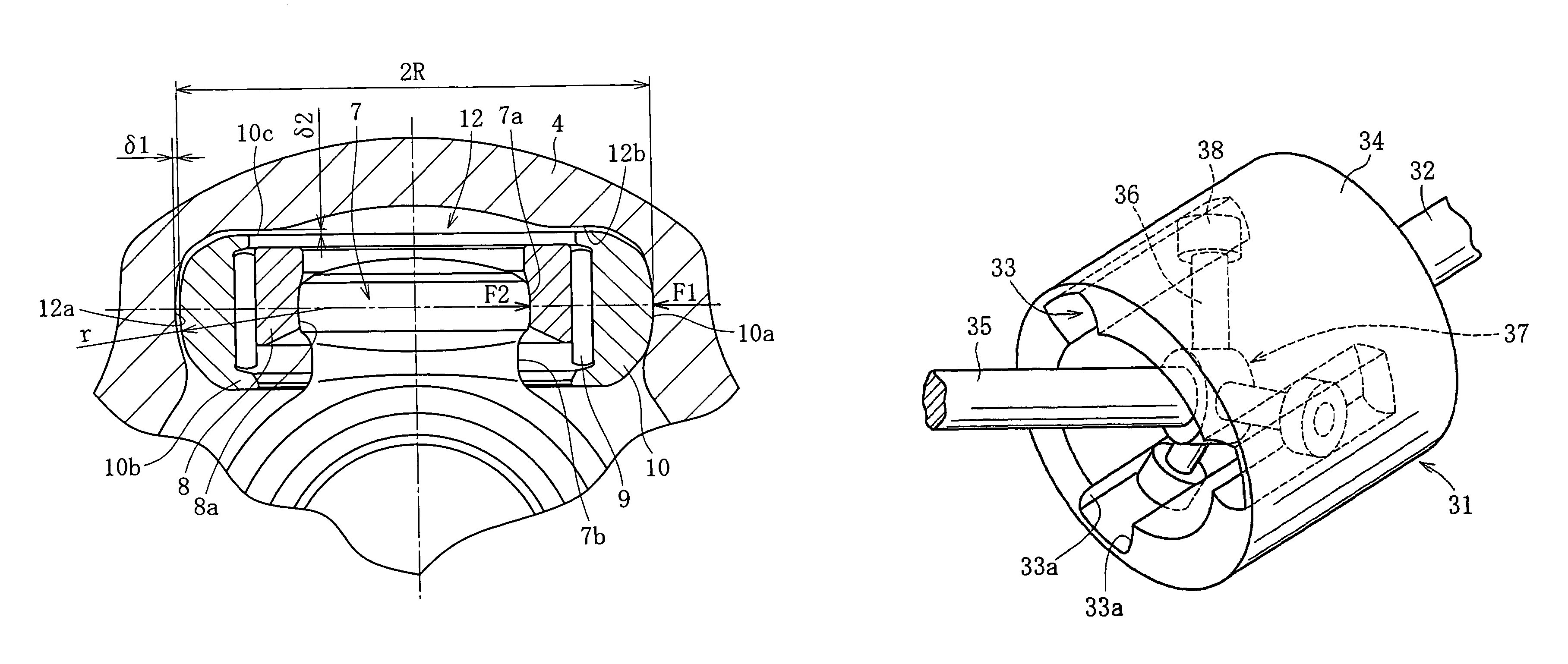
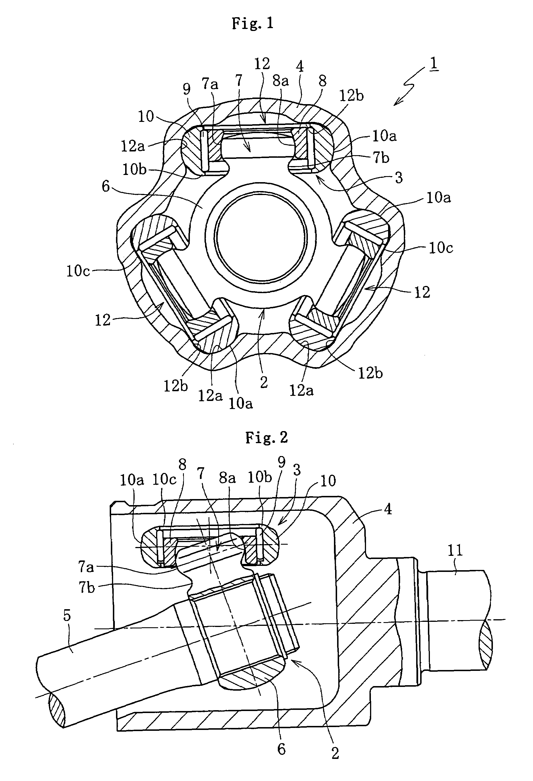
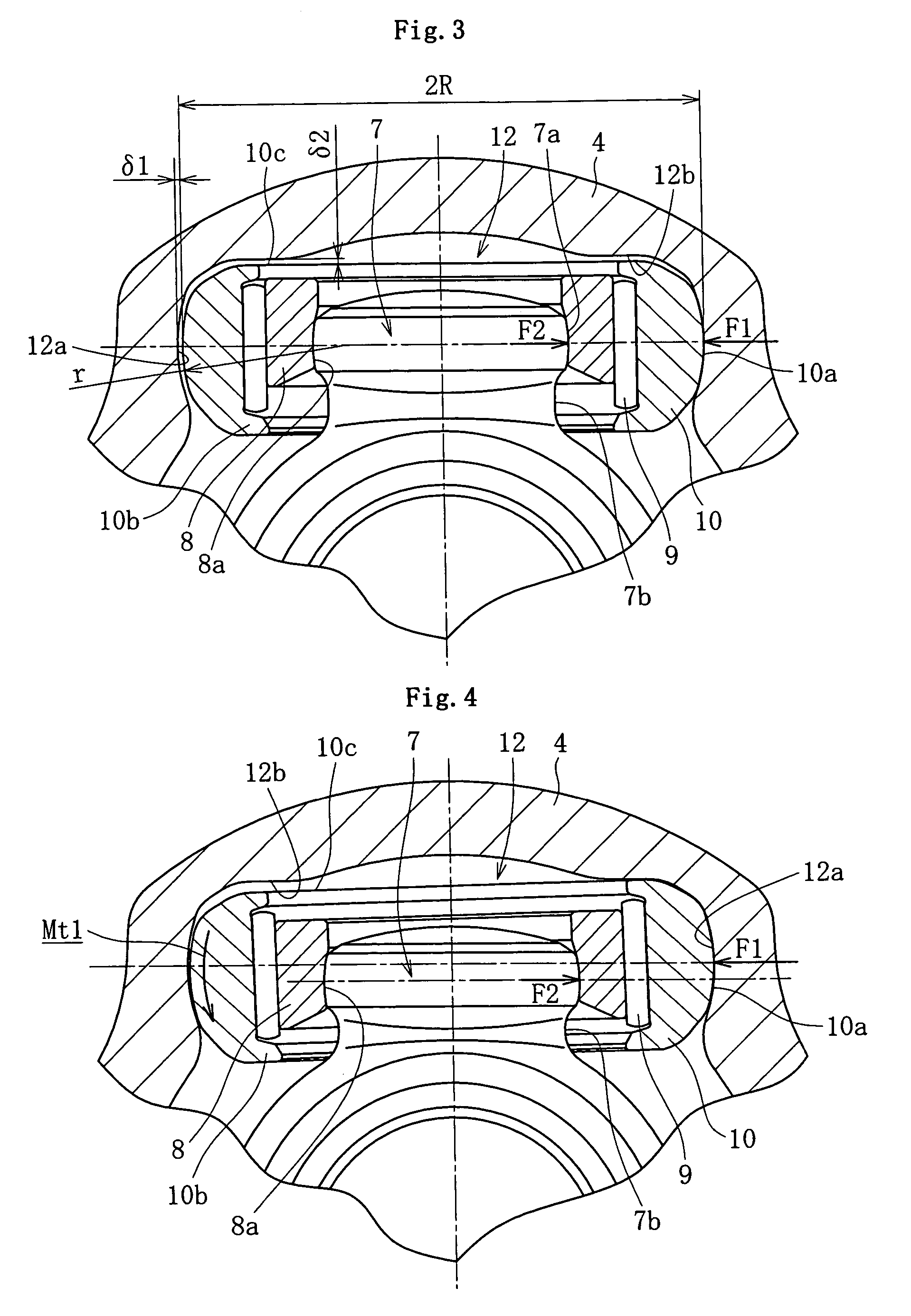
[0036]FIGS. 1 and 2 are cross-sectional views of a tripod type constant velocity universal joint according to one embodiment of the present invention. FIG. 1 shows a cross section perpendicular to a main shaft of the tripod type constant velocity universal joint, while FIG. 2 shows a cross section containing the main axis. The tripod type constant velocity universal joint 1 mainly includes an inner joint member 2, a roller mechanism 3, and an outer joint member 4.

[0037]The inner joint member 2 includes a boss 6 secured to a second rotation shaft 5 such as a driven shaft, and trunnion journals 7 projecting radially and distributed at circumferentially trisectional positions on a boss 6. On the outer circumferential surface of the head of the trunnion journal 7, an approximately convex spherical surface 7a is formed to become convex in a radial direction. Moreover, on the outer...


PUM


Abstract

A tripod type constant velocity universal joint that can suppress generation of shudder by reducing the 3rd order cyclic axial force and has high rotation durability. In a double-roller tripod type constant velocity universal joint, a track gap δ1 between one of the roller guiding surfaces formed on both sides of a track groove, which is on the no-load applied side, and an outer circumferential surface of an outer roller is set to satisfy δ1>0.03 / A. Also, a shoulder gap δ2 between a guide shoulder surface formed at the bottom of the track groove and a side surface of the outer roller is set to satisfy δ2>0.15×A. In both the expressions, a degree of torus A is defined as a ratio of a radius of curvature r of a generatrix of the outer circumferential surface to a radius R of an outer circumference of the outer roller (A=r / R).

Description

BACKGROUND OF THE INVENTION[0001]1. Field of the Invention[0002]The present invention relates to a tripod type constant velocity universal joint used for transmitting a torque between rotation shafts that are incorporated into a drive system of an automobile and are mainly located on a nonlinear line, for example.[0003]2. Description of the Related Art[0004]In a drive shaft of an automobile, or the like, a constant velocity universal joint of a tripod type is frequently used as a constant velocity universal joint on an inboard side of the automobile. As shown in FIGS. 7 and 8, this tripod type constant velocity universal joint 31 includes an outer joint member 34, an inner joint member 37, and rollers 38. The outer joint member 34 is secured to an end of a first rotation shaft 32 such as a drive shaft, has a bottomed cylindrical shape, and includes track grooves 33 extending axially and distributed at circumferentially trisectional positions on its inner circumferential surface. The...

Claims


Application Information

Patent Timeline
Patent Type & Authority Patents(United States)
IPC IPC(8): F16D3/26F16D3/205
CPCF16D3/2055Y10S464/905F16D2003/2026
Inventor IZUMINO, JUNICHIISHIJIMA, MINORUYAMAZAKI, KENTA
Owner NTN CORP
Why Eureka
Try Eureka