Arrangement and use of a slit diaphragm
a diaphragm and slit technology, applied in the direction of instruments, radiation pyrometry, material analysis, etc., can solve the problems of high cost, complex structure of devices, and inability to continuously adjust the slit width, etc., to achieve the effect of achieving objects, and achieving objects is also costly, and the cost of manufacturing is high
- Summary
- Abstract
- Description
- Claims
- Application Information
AI Technical Summary
Benefits of technology
Problems solved by technology
Method used
Image
Examples
first embodiment
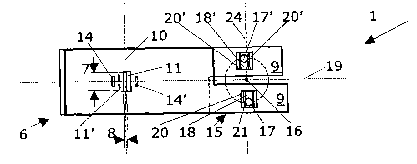
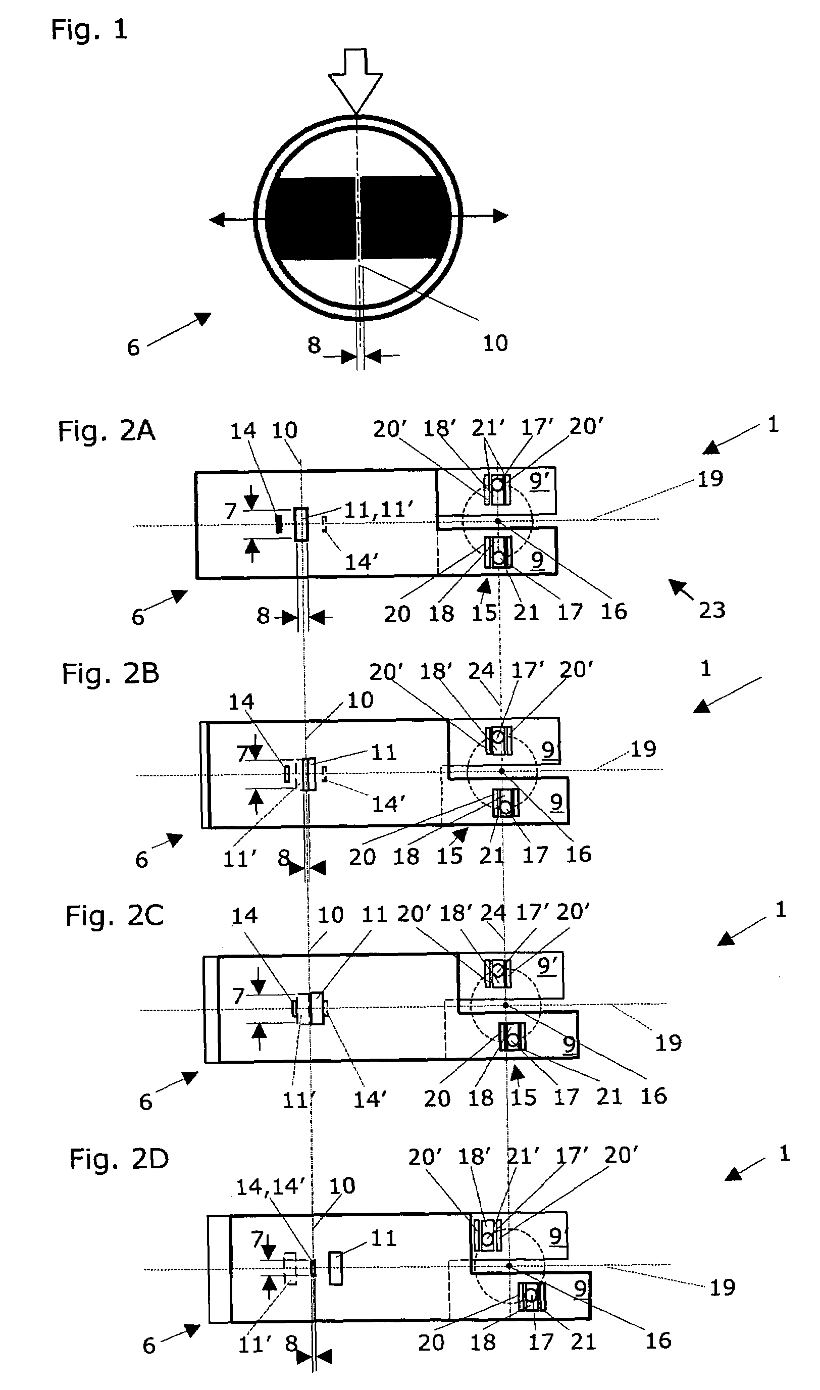
[0028]FIG. 2, in its various sections FIGS. 2A to 2D, shows a front view of a slit diaphragm according to the present invention in a first embodiment, having two slides positioned on two separate parallel lines for varying the slit width or the slit height. A device 1 is shown for delimiting a field 3 (cf. FIGS. 5 and 6) impinged by light from a light source 2 (cf. FIG. 5), particularly on the surface of an optical element 4 (FIG. 6) and / or a sample 5 (FIG. 5). Optical elements 4 include all typical optical components, such as gratings, mirrors, fiber-optic cables, lenses, and the like. Samples 5 include fluids, such as solutions, suspensions, and liquid-gas mixtures, as well as solids, such as emulsions, tissue sections, and cell cultures. The device 1 includes a slit diaphragm 6 having a slit height 7 and a slit width 8, the slit width 8 and / or the slit height 7 being continuously adjustable. The device 1 according to the present invention is distinguished in that the slit diaphra...
second embodiment
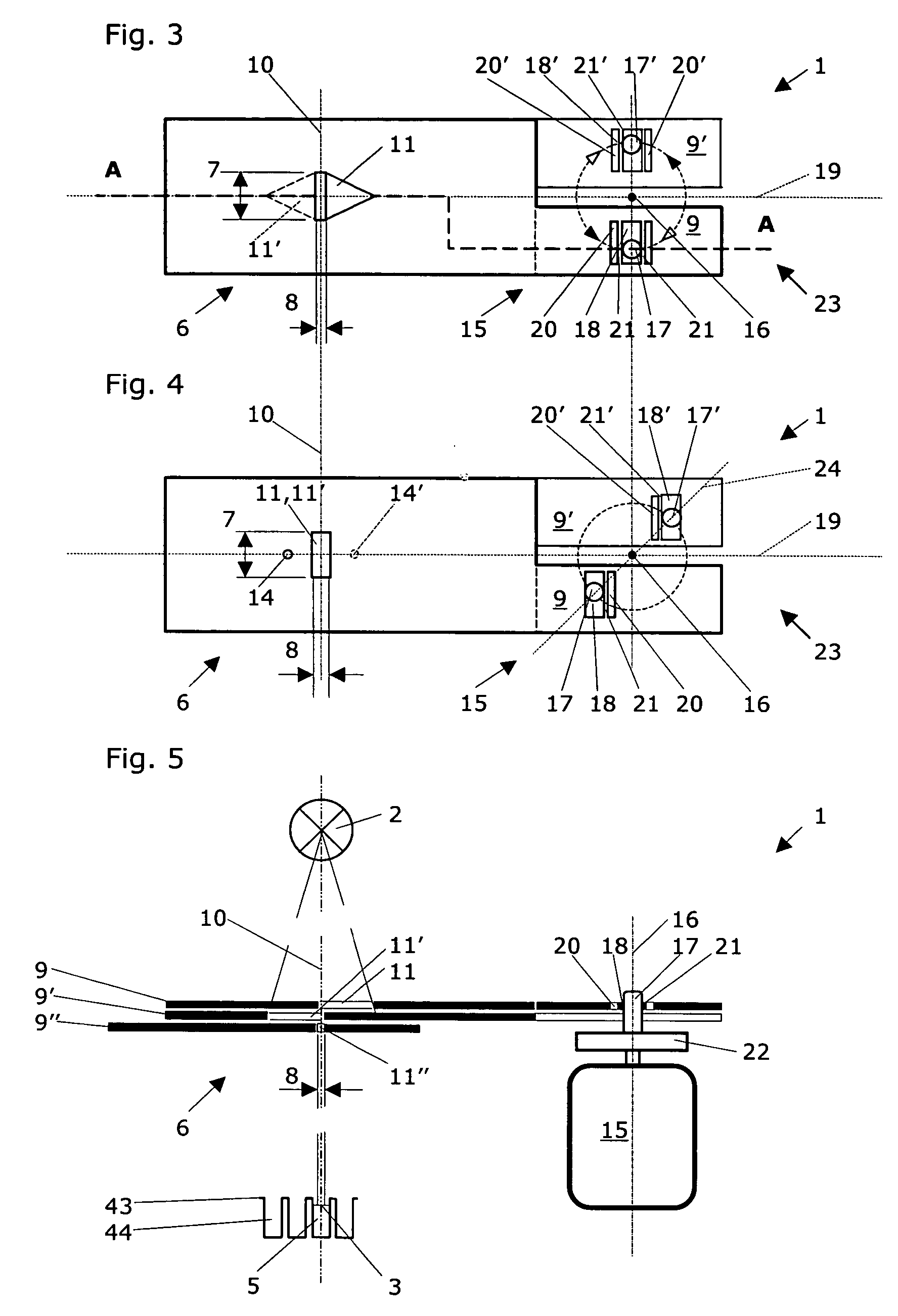
[0037]FIG. 3 shows a front view of a slit diaphragm according to the present invention in a second embodiment, having two slides positioned on two separate parallel lines for varying the slit width and / or slit height, in a first slide position, in which the two slides are essentially congruent to one another and define a specific slit width and a maximum slit height. The optical openings 11, 11′ in the two slides 9, 9′ have a pentagonal shape and are mirror-symmetric to one another here. Through a slight rotation of the rotating disk 22 using the motor drive 15 in the counterclockwise direction (solid arrow tip) around the center of rotation 16, the slides 9, 9′ are moved toward one another in such a way that the slit height 7 remains unchanged, but the slit width 8 is reduced (similarly to FIG. 2). By rotating the rotating disk 22 using the motor drive 15 counterclockwise (empty arrow tip) around the center of rotation 16, the slides 9, 9′ are moved toward one another in such a way...
fourth embodiment
[0038]If this increase of the slit width 8 is not desired—according to the slit diaphragm according to the present invention—a third slide 9″, positioned on a further separate, parallel line, having a narrow optical opening 11″ which defines a fixed slit width 8, may be positioned symmetrically to the optical axis in such a way (cf. FIG. 5) that with increasing movement of the rotating disk 22 clockwise, the slit height 7 may be varied while the slit width now remains the same.
PUM
| Property | Measurement | Unit |
|---|---|---|
| angle | aaaaa | aaaaa |
| angle | aaaaa | aaaaa |
| height | aaaaa | aaaaa |
Abstract
Description
Claims
Application Information
 - R&D
- Intellectual Property
- Life Sciences
- Materials
- Tech Scout
- Unparalleled Data Quality
- Higher Quality Content
- 60% Fewer Hallucinations
Browse by: Latest US Patents, China's latest patents, Technical Efficacy Thesaurus, Application Domain, Technology Topic, Popular Technical Reports.
© 2025 PatSnap. All rights reserved.Legal|Privacy policy|Modern Slavery Act Transparency Statement|Sitemap|About US| Contact US: help@patsnap.com


