

Method and device for monitoring switchgear in electrical switchgear assemblies
a technology of electrical switchgear and switchgear assembly, which is applied in the direction of protective switch details, emergency protective arrangements for limiting excess voltage/current, instruments, etc., can solve the problems of reducing the accuracy of maintenance, increasing the risk of damage during maintenance, and ignoring current measurement errors in cases of overcurrent for determining arcing energy and contact wear. , to achieve the effect of reducing maintenance costs, increasing the accuracy of contact wear calculations, and increasing the precision of contact wear calculations
- Summary
- Abstract
- Description
- Claims
- Application Information
AI Technical Summary
Benefits of technology
Problems solved by technology
Method used
Image

Examples
Embodiment Construction
[0005]The object of the present invention is to provide a method, a computer program, a device and a switchgear assembly having such a device for improved and simplified monitoring of switchgear in electrical switchgear assemblies. This object is solved by the features of the independent claims.
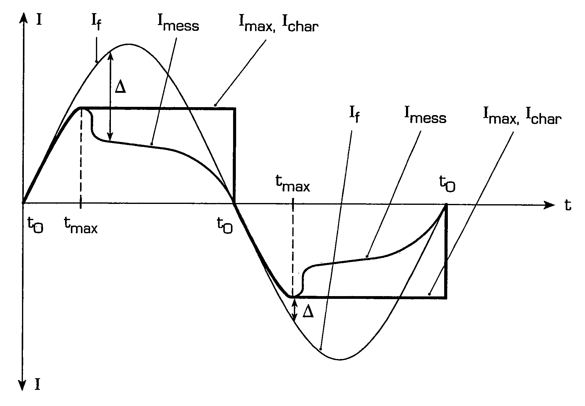
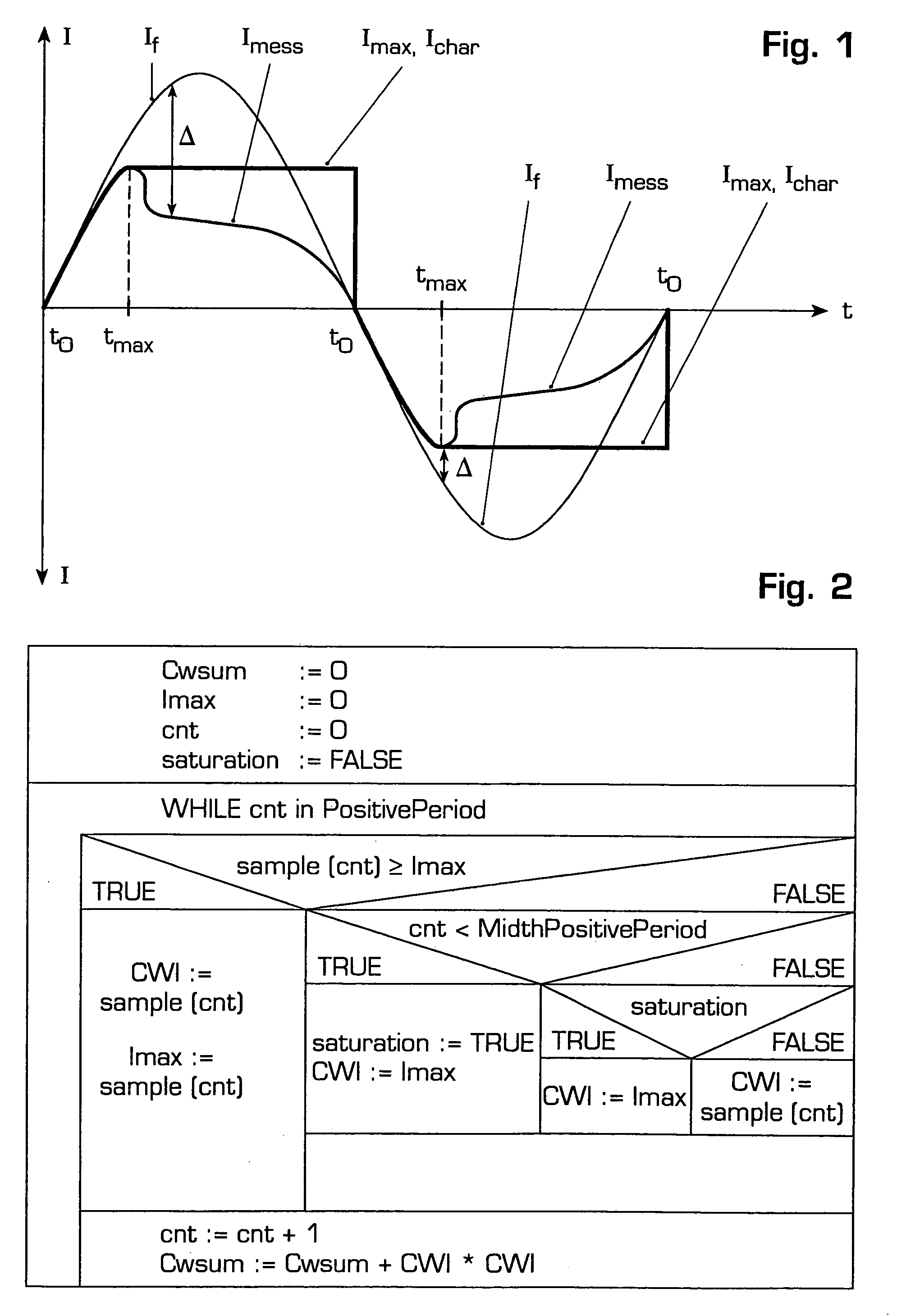
[0006]In a first aspect the invention consists in a method for determining contact wear in an electrical switchgear, especially in electric switchgear assemblies for high and medium voltage, wherein a contact current flowing through the switchgear during a switching action is recorded using a current transformer and is evaluated with regard to contact wear, wherein in order to determine a status variable characterising the contact wear, a current measuring signal of the current transformer is first measured as a function of the time, in the event of deviations between the predicted contact current and the current measuring signal, the presence of a measurement error is detected and in the eve...
PUM
 Abstract
Description
Claims
Application Information