Electronic product having airflow-guiding device

a technology of airflow and guiding device, which is applied in the direction of insulated conductors, power cables, cables, etc., can solve the problems of reducing the heat dissipation efficiency of the system fan module, affecting the efficiency of the airflow guiding effect of other electronic modules, and serious overheating problems in electronic modules. , to achieve the effect of enhancing the airflow guiding effect, reducing the difficulty level of processing a design change, and reducing the manufacturing cos

Active Publication Date: 2006-10-17
QUANTA COMPUTER INC
View PDF12 Cites 18 Cited by
  • Summary
  • Abstract
  • Description
  • Claims
  • Application Information

AI Technical Summary

Benefits of technology

[0006]It is an object of the present invention to provide an electronic product having an airflow-guiding device for lowering the cost for fabricating partitions and lowering the difficulty level of processing a design change.
[0007]It is another object of the present invention to provide an electronic product having an airflow-guiding device for flexibly distributing airflow so as to increase airflow-guiding effect.
[0008]It is another object of the present invention to provide an electronic product having an airflow-guiding device for simplifying the mechanism for assembling a metal plate partition with the housing of the electronic product, so as to briefly disassemble and assemble the metal plate partition.
[0010]According to a preferred embodiment of the present invention, the electronic product having the airflow-guiding device comprises: a housing body, an electronic module group located in the housing body; at least one power supply, at least one system fan module, and at least one metal plate partition. The power supply is located in at least one passage between the electronic module group and the housing body. The system fan module is located on one end of the housing body and exposed to the ambience, and is used for introducing the ambient airflow into the housing body, thereby providing the heat-dissipation function for the electronic module group. The metal plate partition is installed on an air inlet of the passage facing towards the system fan module, thereby reducing the air flowing from the system fan module into the power supply.
[0016]Hence, with the application of the present invention, the fabrication cost of partitions and the difficulty level of processing a design change can be lowered; the airflow can distributed flexibly, thus enhancing the airflow-guiding effect; and the mechanism for assembling the metal plate partitions and the housing can be simplified, thereby briefly disassembling and assembling the metal plate partitions.

Problems solved by technology

When the fans of the power supplies and the system fan modules are working at the same time, the air pressures in the areas of power supplies are usually lower than those in the areas of other electronic modules, so that most of the airflow flows naturally into the power supplies after entering the housing of the electronic product from the ambiance, resulting in the other electronic modules lacking of airflow passing through.
Thus, the heat-dissipation efficiency of the system fan modules decreases and the over-heat problem is seriously in the electronic modules.
In other words, the fans of the power supplies carry away most of the airflow in the housing, thus resulting in the electronic modules failing to have effective heat-dissipation.
However, the conventional plastic wind-shielding partition costs quite a lot of molding expense, and has the difficulty of design modification.
Additionally, the mechanism for assembling the conventional wind-shielding partition with the housing of the electronic product is quite complicated, so that the disassembling and assembling steps cannot be briefly done, and also the wind-shielding partition is frequently damaged thereby.
Moreover, the power supplies and the electronic modules all need proper amounts of airflow flowing therein, but it is very difficult to distribute airflow flexibly with the conventional plastic wind-shielding partition, i.e. the conventional plastic wind-shielding partition has poor airflow-guiding effect.

Method used


Image

  • Electronic product having airflow-guiding device
  • Electronic product having airflow-guiding device
  • Electronic product having airflow-guiding device

Examples


Embodiment Construction

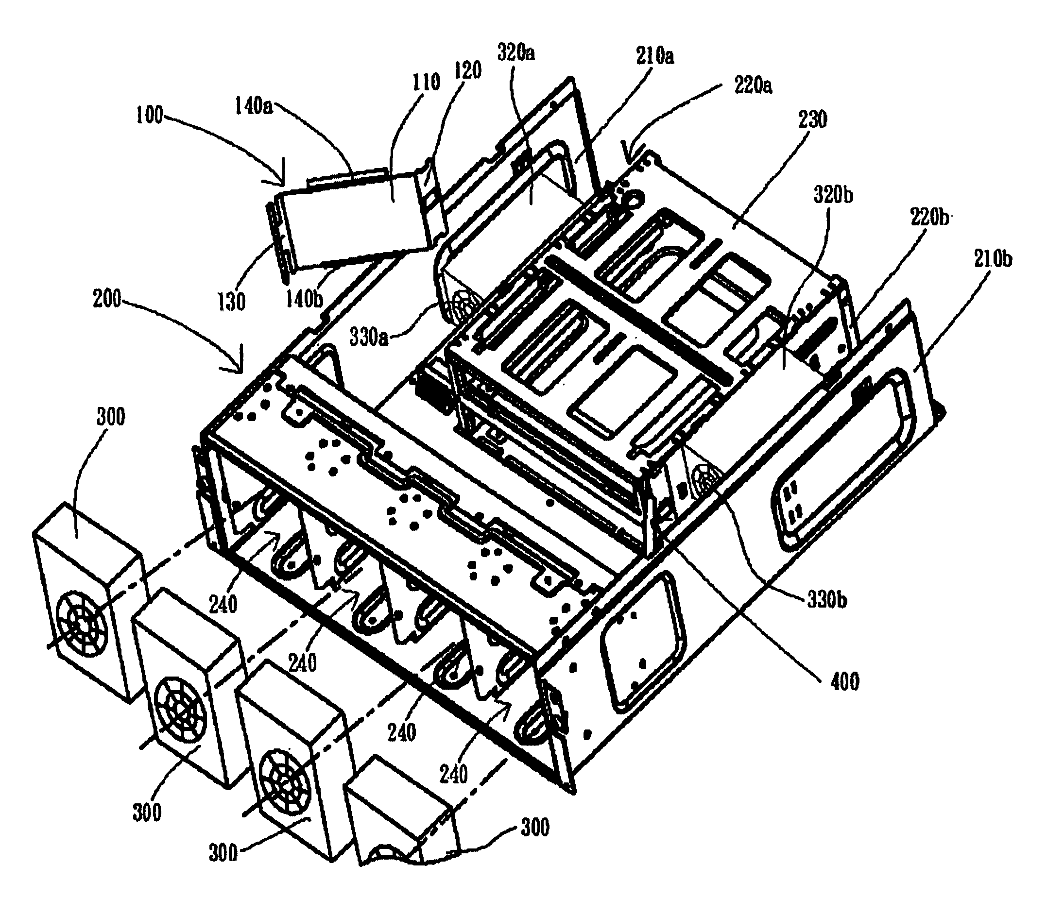
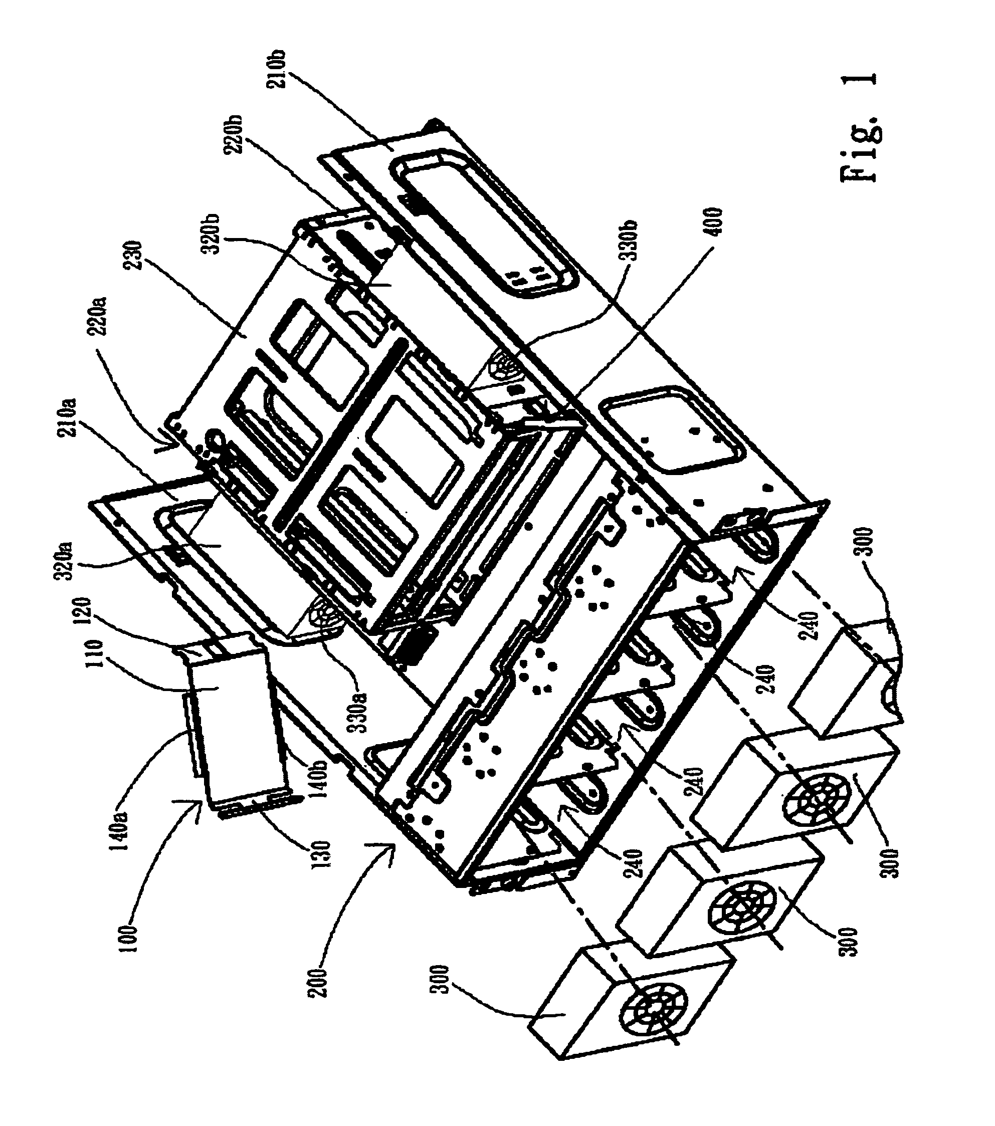
[0022]Referring to FIG. 1, FIG. 1 is a 3-D schematic diagram showing the assembly of system fan modules and an electronic product having an airflow-guiding device, according to a preferred embodiment of the present invention. The electronic product (such as an industrial computer or a server) of the present invention has a housing body 200, and in the housing body 200, there are an electronic module group 230, at least one power supply (such as two power supplies 320a and 320b), a plurality of system fan modules 300 (such as four system fan modules), and at least one metal plate partition (such as two metal plate partitions; metal plate partitions 100 and 400), wherein the electronic module group 230 is composed of a plurality of electronic modules (such as storage controllers; hard disk drives), and the electronic modules are generally installed in the central position of the housing body 200 with a vertically stacking pattern. A module partition 220a and a module partition 220b ar...


PUM


Abstract

An electronic product (for example: an industrial computer) having an airflow-guiding device is disclosed, thereby preventing most of the airflow from being carried away by power supplies, wherein most of the air flow directed towards the power supplies will result in other electronic modules failing to have proper heat-dissipation. The present invention is to install metal partition plates on the inlets of air passages among the power supplies, fan modules and both sides of the electronic modules in the electronic product, wherein each of the meal partition plate is composed of a partition main body; folded plated respectively connected to two opposite sides of the partition main body; and buffer elements (for example: sponge pads) covering portions of the other two opposite sides of the partition main body.

Description

FIELD OF THE INVENTION[0001]The present invention relates to an electronic product having an airflow-guiding device, and more particularly, to the electronic product effective using airflow for heat dissipation by preventing most of the airflow from being carried away by power supplies.BACKGROUND OF THE INVENTION[0002]It is a common technique to use fans in various industrial equipments for heat dissipation, especially in widely used electronic products. With the increase of various applications, the number of electronic modules installed in one single electronic product also increases. Based on the design consideration of space, the electronic modules are usually stacked vertically in a housing of an electronic product. For example, there are quite many electronic modules (such as storage controllers) existing in an industrial computer or server. For the considerations of providing sufficient power to the electronic modules and providing backup power source, the electronic product ...

Claims


Application Information

Patent Timeline
Patent Type & Authority Patents(United States)
IPC IPC(8): H05K7/20G06F1/20
CPCG06F1/20H05K7/20727
Inventor CHEN, YU-LIN
Owner QUANTA COMPUTER INC
Why Eureka
Try Eureka