Radio relay apparatus

Inactive Publication Date: 2006-10-17
MARUKO IND
View PDF13 Cites 14 Cited by
  • Summary
  • Abstract
  • Description
  • Claims
  • Application Information

AI Technical Summary

Benefits of technology

[0006]An object of the present invention is to provide a radio relay apparatus capable of in

Problems solved by technology

The long coaxial cable exhibits larger transmission loss, resulting in consuming a large qu

Method used


Image

  • Radio relay apparatus
  • Radio relay apparatus
  • Radio relay apparatus

Examples


Embodiment Construction

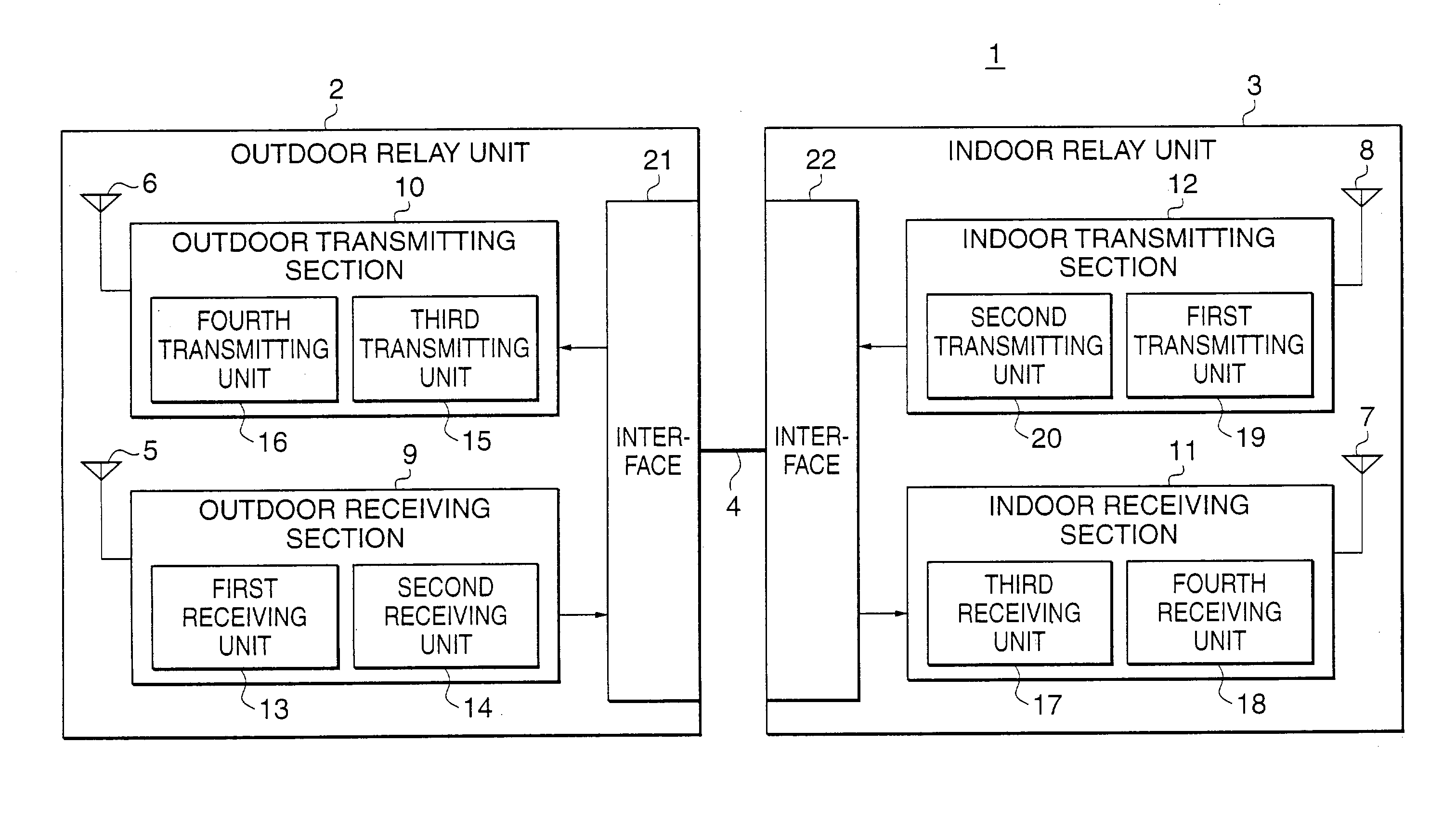
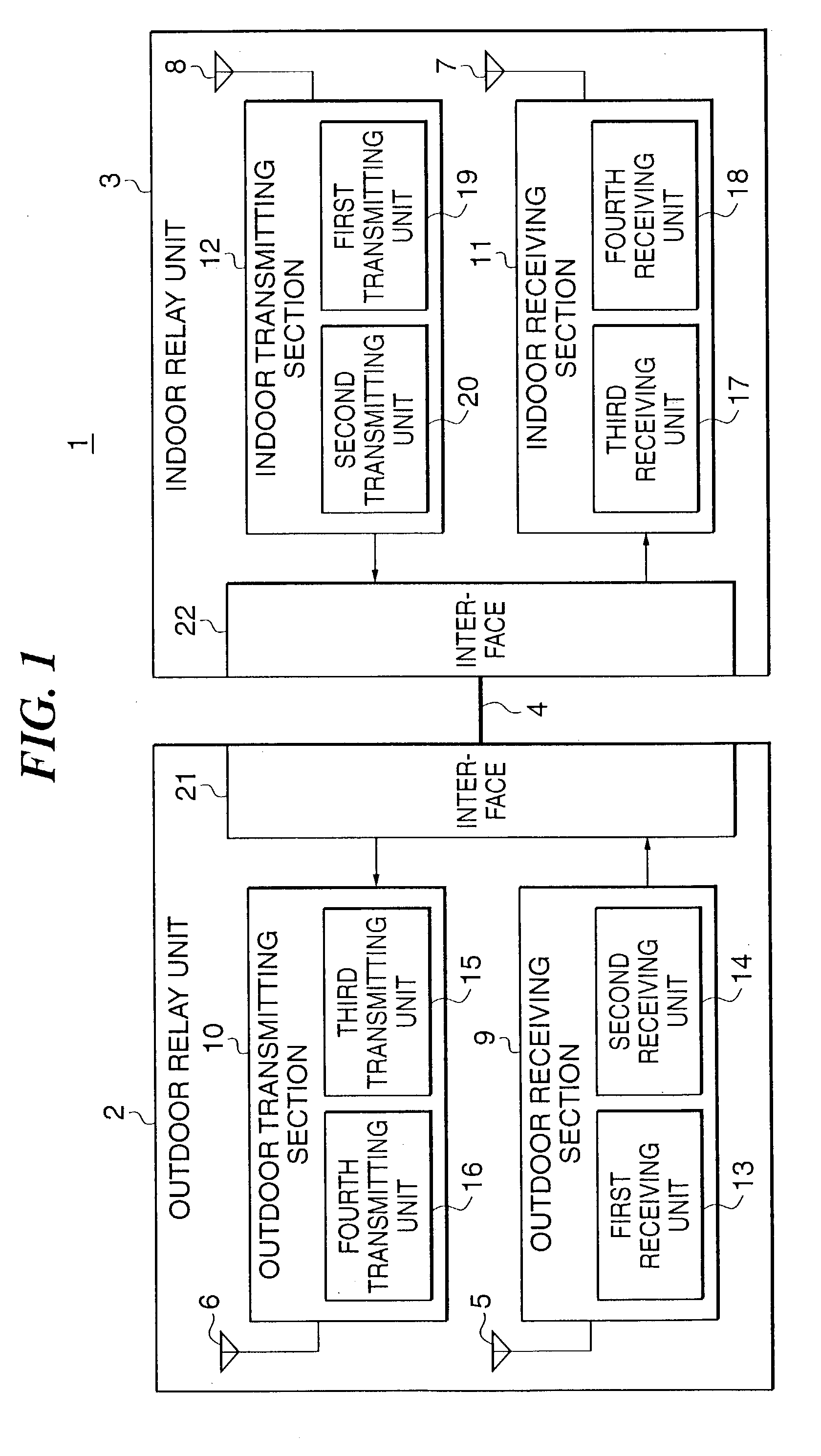
[0039]A radio relay apparatus 1 illustrated in FIG. 1 according to the present invention is incorporated in a mobile communication system. The radio relay apparatus 1 comprises an outdoor relay unit 2 serving as a first relay unit, an indoor relay unit 3 serving as a second relay unit, and a digital transmission line 4 for connecting the outdoor and indoor relay units 2 and 3 with each other. The outdoor relay unit 2 is equipped out of door and incorporates antennas 5 and 6 for receiving and transmitting carrier waves. The indoor relay unit 3 is equipped in the blind area such as an underground area and tunnel, which hinders the arrival of the carrier waves from a transmission base station. The indoor relay unit 3 incorporates antennas 7 and 8 for receiving the transmitting carrier waves.

[0040]The outdoor relay unit 2 is provided with an outdoor receiving section 9 and an outdoor transmitting section 10. The outdoor receiving section 9 includes the antenna 5 for picking up the carri...


PUM


Abstract

A radio relay apparatus including an outdoor relay unit formed of first and second receiving parts equipped out of doors and an indoor relay unit formed of third and fourth receiving parts, and a digital transmission line connecting the outdoor and indoor relay units enables radio communication even in a blind area such as an underground area and tunnel. In the first receiving part of the outdoor relay unit, a receiving antenna for receiving a high-frequency signal is integrally incorporated so as eliminate the transmission loss. The high-frequency analog signal is converted to its corresponding digital signal of a desired frequency band by a digital signal processor in the outdoor relay unit, and then, the digital signal thus obtained is transmitted to the indoor relay unit through the digital transmission line, so that high-quality radio communication can be accomplished.

Description

BACKGROUND OF THE INVENTION[0001]1. Field of the Invention[0002]This invention relates to a radio relay apparatus for use in a mobile communication system, and more particularly to a radio relay apparatus for establishing radio communication in a none sensitive area (blind zone) such as an underground area and tunnel, which has difficulty in communicating due to bad radio transmission.[0003]2. Description of the Prior Art[0004]There has been used a radio relay apparatus for allowing communication in a none sensitive area. The radio relay apparatus is connected to an outdoor receiving antenna through a coaxial cable, which is attached to a relay apparatus located in the none sensitive area, so as to transmit a communication signal to the relay apparatus through the coaxial cable.[0005]In general, the coaxial cable connecting the radio relay apparatus to the receiving antenna is as long as over 100 meters in the majority of cases. The long coaxial cable exhibits larger transmission lo...

Claims


Application Information

Patent Timeline
IPC IPC(8): H04B17/02H04B3/36H04B7/17H04L25/20H04L25/52H04B7/15H04B17/40
CPCH04B3/36
Inventor OGAWA, NOBORU
Owner MARUKO IND
Why Eureka
Try Eureka