
Wireless telephone and wireless telephone system

a wireless telephone and telephone system technology, applied in the field of wireless telephone and wireless telephone system, can solve the problem that the user cannot be informed of the operating state of the called telephone in the user's original representation form, and achieve the effect of improving the service of the user

Inactive Publication Date: 2006-10-17
RPX CORP
View PDF16 Cites 8 Cited by
  • Summary
  • Abstract
  • Description
  • Claims
  • Application Information

AI Technical Summary

Benefits of technology

[0010]According to the above-described constructions, by transmitting the operating state informing data registered previously in the called telephone to the calling telephone, the calling telephone can be informed of the operating state of the called telephone. Accordingly, unlike the related art in which operating state informing data are registered in a network system, a user can be informed of the operating state of the called telephone in the user's original representation form. Accordingly, it is possible to improve service of the user.
[0012]According to this construction, in the case where the wireless telephone receives the call setting accepted data from the called telephone or a network system which is a transit system, the wireless telephone informs the operating state of the called telephone on the basis of the operating state informing data registered in the wireless telephone. Accordingly, a user of a calling wireless telephone can be informed of the operating state of the called telephone in the user's original representation form. Accordingly, it is possible to improve service for the user.
[0014]According to this construction, the operating state informing data inputted from the wireless telephone and registered in the network system is transmitted to the calling mobile telephone. Accordingly, unlike the related art in which operating state informing data are previously registered in the network system in such a manner that a user of the wireless telephone cannot at all touch them, the user can be informed of the operating state of the called telephone in the user's original representation form. Accordingly, with this construction as well, it is possible to improve service of the user.

Problems solved by technology

This leads to the problem that a user cannot be informed of the operating state of the called telephone in the user's original representation form.

Method used


Image

  • Wireless telephone and wireless telephone system
  • Wireless telephone and wireless telephone system
  • Wireless telephone and wireless telephone system

Examples


embodiment 1

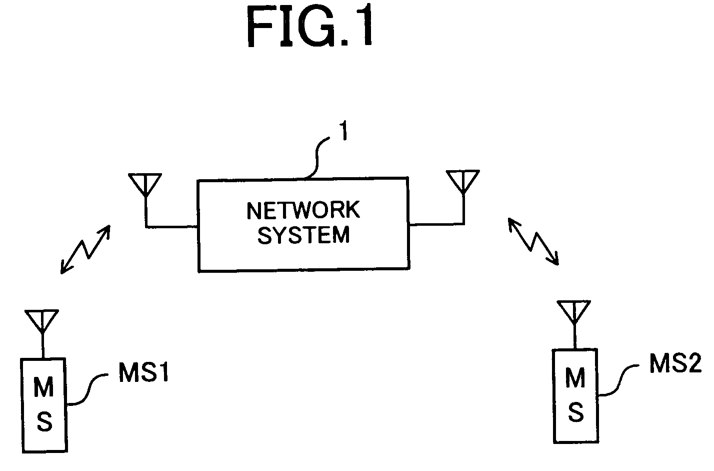
[0031]FIG. 1 is a conceptual diagram showing the entire construction of a mobile telephone system using wireless telephones according to embodiment 1 of the invention. This mobile telephone system conforms to, for example, 3G (3 Generation) standards such as W-CDMA, UMTS (Universal Mobile Telecommunication System) and cdma2000, 2.5G (2.5 Generation) standards such as IS-95, or 2G (2 Generation) standards such as PDC (Personal Digital Cellular) and GSM (Global System for Mobile Communications), and is provided with a plurality of mobile telephones MS1 and MS2 (hereinafter also referred to generally as “mobile telephone MS”) and a network system 1.

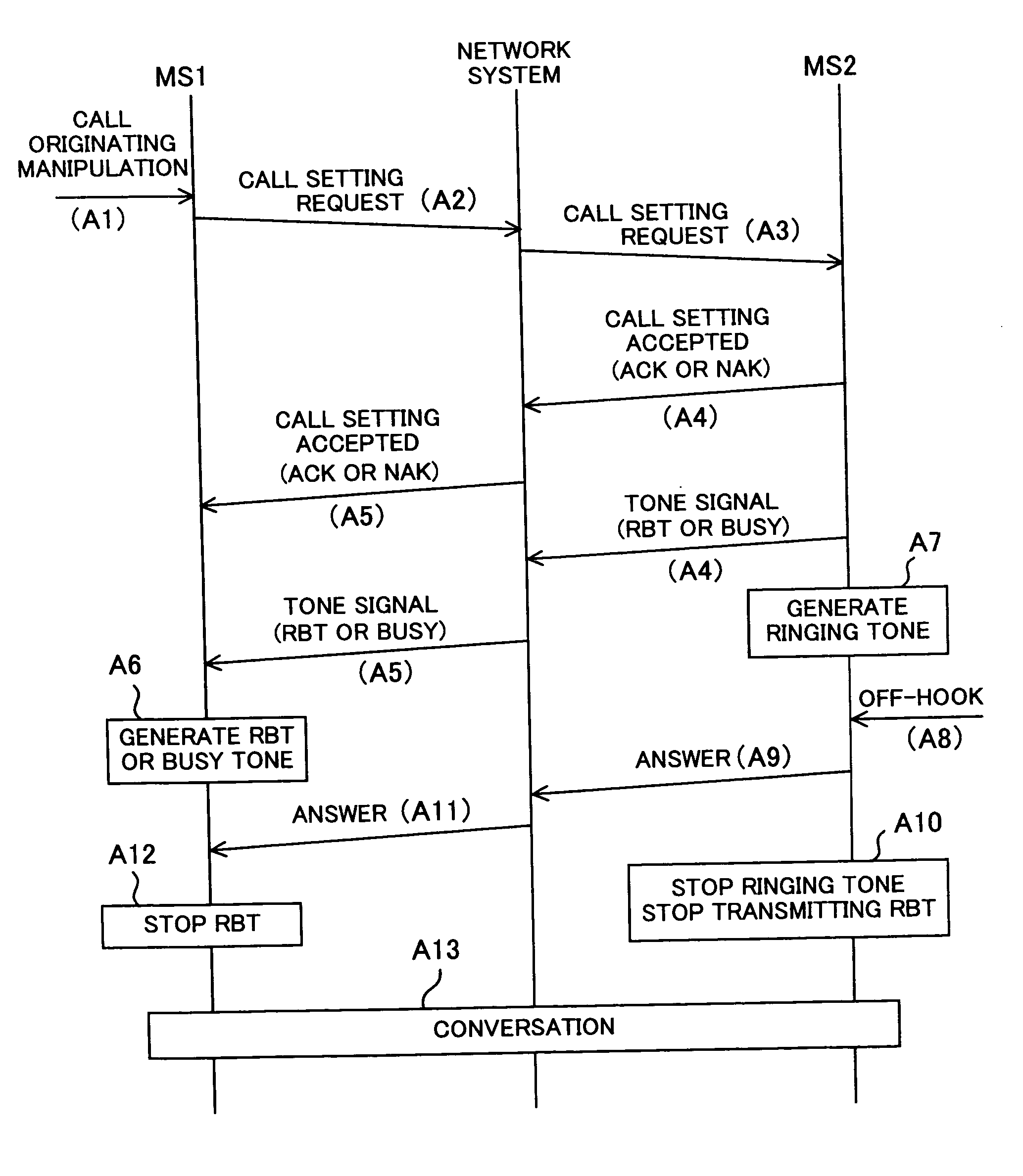
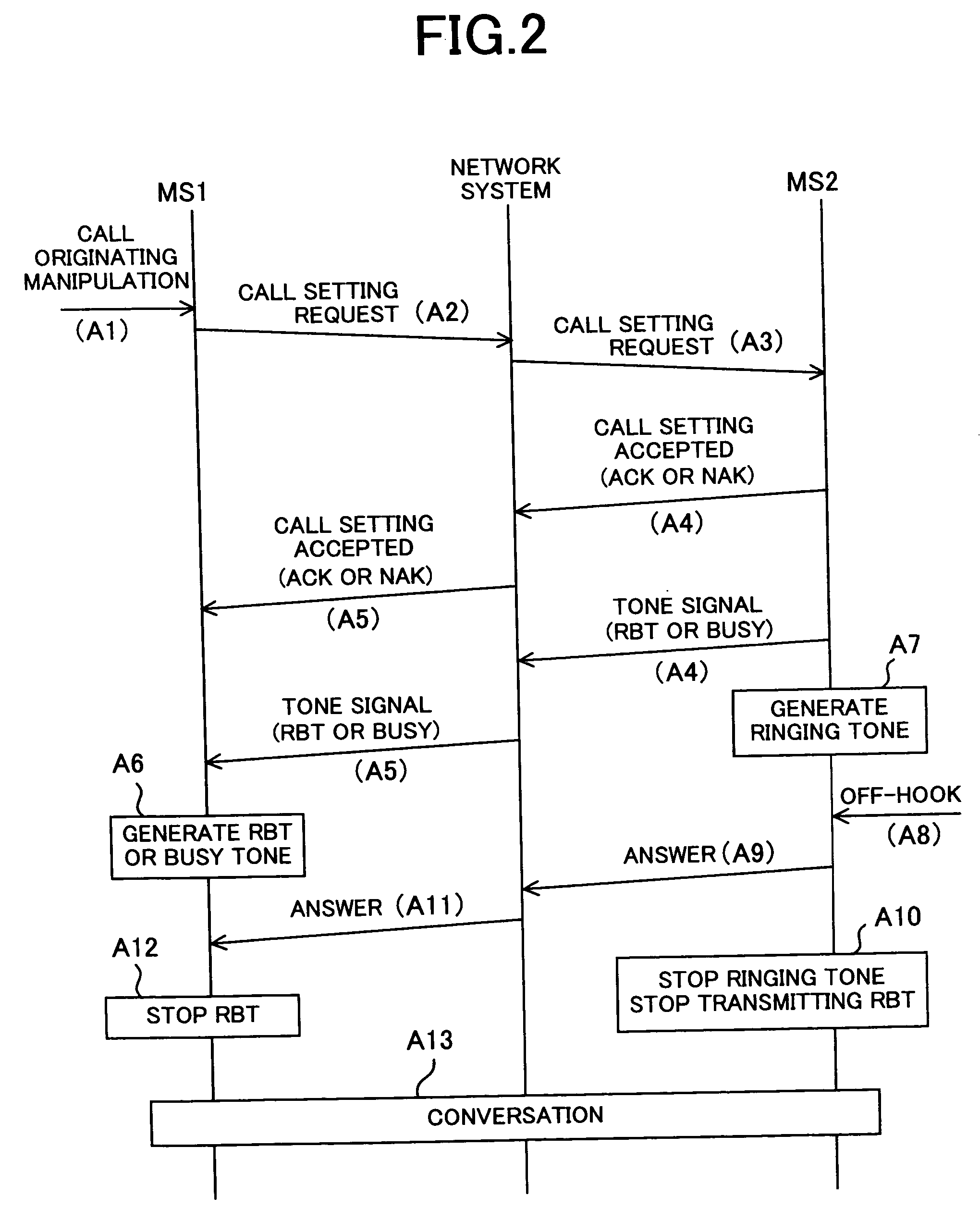
[0032]FIG. 2 is a sequence diagram for explaining call setting processing in the above-described mobile telephone system. For example, consideration will be given to a case where a call is made from one mobile telephone (hereinafter referred to as “calling mobile telephone”, as the need arises) MS1 to another mobile telephone (hereinafter re...

embodiment 2

[0062]FIG. 7 is a sequence diagram for explaining processing during call setting in a mobile telephone system according to embodiment 2 of the invention.

[0063]In the above-described embodiment 1, the tone data registered in the called mobile telephone MS2 is transmitted to the calling mobile telephone MS1, whereby the user's original melody or sound of the called mobile telephone MS2 is generated from the calling mobile telephone MS1. In contrast, in this embodiment 2, tone data is previously registered not in the called mobile telephone MS2 but in the calling mobile telephone MS1, and in the case where the calling mobile telephone MS1 receives call setting accepted data after having originated a call, the calling mobile telephone MS1 generates an RBT or a busy tone on the above-described registered tone data. In this manner, the user of the calling mobile telephone MS1 can hear an original RBT or busy tone suited to the user's preference from his / her own mobile telephone MS. Accord...

embodiment 3

[0070]FIG. 8 is a block diagram showing the internal construction of the mobile telephone MS according to embodiment 3. In FIG. 8, the same reference numerals are used to denote the same functional parts as those shown in FIG. 3.

[0071]In the above-described embodiment 1 or 2, dedicated tone data are registered in the mobile telephone MS as RBT and busy tone. In contrast, in this embodiment 3, ringing tone data already registered in the mobile telephone MS as data for generating a ringing tone is utilized as data for RBT or busy tone. Accordingly, embodiment 3 has the advantage that the mobile telephone MS does not need a storage area dedicated to tone data.

[0072]More specifically, ringing tone data, in addition to user data, is stored in the second memory part 14 of the mobile telephone MS according to this embodiment 3. The ringing tone data is data on a ringing tone to be generated when an incoming call is received, and, for example, is stored previously or is stored by being down...


PUM


Abstract

In a related art mobile telephone system, the generation of an RBT (ring back tone) and a busy tone is realized by transmitting data registered in a network system to a calling telephone. In a mobile telephone system according to this invention, RBT data and the like are previously registered in a called telephone, and when a calling telephone originates a call to this called telephone, data corresponding to an operating state of the called telephone is transmitted to the calling telephone. Accordingly, an RBT and the like can be easily changed with a user's original melody or the like, whereby it is possible to improve service for the user.

Description

TECHNICAL FIELD[0001]This invention relates to a wireless telephone and a wireless telephone system for use in a mobile telephone system such as W-CDMA (WidebandCode Division Multiple Access) and cdma2000.BACKGROUND OF THE INVENTION[0002]According to a related art, the case where a call is made from a mobile telephone which is one kind of wireless telephone to another mobile telephone or a fixed telephone and the like, the calling mobile telephone generates a tone corresponding to the operating state of the called telephone. For example, in the case where the calling mobile telephone is calling the called telephone, the calling mobile telephone generates a ring back tone. In the case where the called telephone is busy, the calling mobile telephone generates a busy tone. In addition, in the case where the called telephone is a mobile telephone and exists out of a service area, the calling mobile telephone generates a voice such as “the telephone you calls is turned off or is in a pl...

Claims


Application Information

Patent Timeline
IPC IPC(8): H04M3/42H04M1/724H04M19/04H04W4/16
CPCH04M1/72519H04M19/04H04W4/16H04M1/724
Inventor SEKI, SHUICHI
Owner RPX CORP
Learn More